Input Circuit
Input Signal COS Timing Rules
Stop State—SO turns Off when
3
: Run State—SO turns On when
4
:
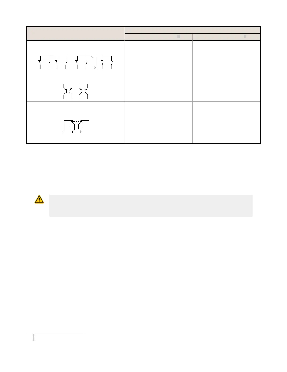
2X Complementary A and B
4 Terminals 5 Terminals
PNP
24V
OFFON OFFON
At least 1 channel (A or B) within a pair of
contacts is in the Stop state.
Simultaneous: A and B are concurrently
in the Stop state, then contacts within a
channel in the Run state within 400 ms
(150 ms for two-hand control), both
channels are in the Run state within 3
seconds (0.5 seconds for two-hand
control).
Concurrent: A and B are concurrently in
the Stop state, then contacts within a
channel in the Run state within 3 seconds.
Both channels are in the Run state with no
simultaneity.
4-Wire Safety Mat
One of the following conditions is met:
• Input channels are shorted
together (normal operation)
• At least 1 of the wires is
disconnected
• One of the normally low
channels is detected high
• One of the normally high
channels is detected low
Each channel detects its own pulses.
Signal Debounce Times
Closed-to-Open Debounce Time (from 6 ms to 1000 ms in 1 ms intervals, except 6 ms to 1500 ms for mute
sensors). The closed-to-open debounce time is the time limit required for the input signal to transition from the high (24
V dc) state to the steady low (0 V dc) state. This time limit may need to be increased in cases where high-magnitude
device vibration, impact shock, or switch noise conditions result in a need for longer signal transition times. If the
debounce time is set too short under these harsh conditions, the system may detect a signal disparity fault and lock out.
The default setting is 6 ms.
CAUTION: Debounce and Response
Any changes in the debounce times may affect the Safety Output response (turn Off) time.
This value is computed and displayed for each Safety Output when a configuration is created.
Open-to-Closed Debounce Time (from 10 ms to 1000 ms in 1 ms intervals, except 10 ms to 1500 ms for mute
sensors). The open-to-closed debounce time is the time limit required for the input signal to transition from the low (0 V
dc) state to the steady high (24 V dc) state. This time limit may need to be increased in cases where high magnitude
device vibration, impact shock, or switch noise conditions result in a need for longer signal transition times. If the
debounce time is set too short under these harsh conditions, the system may detect a signal disparity fault and lock out.
The default setting is 50 ms.
3
Safety Outputs turn Off when one of the controlling inputs is in the Stop state.
4
Safety Outputs turn On only when all of the controlling inputs are in the Run state and after a manual reset is performed (if any safety inputs are
configured for Manual reset and were in their Stop state).
XS/SC26-2 Safety Controller
70
 Loading...


