5
Specifications and Requirements
5.1 XS/SC26-2 Specifications
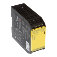
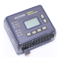
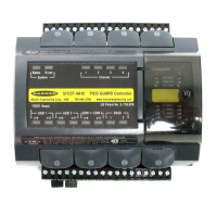
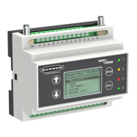
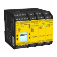
Base Controller and Expansion Modules
Mechanical Stress
Shock: 15
g
for 11 ms, half sine, 18 shocks total (per IEC
61131-2)
Vibration: 3.5 mm occasional / 1.75 mm continuous at 5 Hz to 9
Hz, 1.0
g
occasional and 0.5
g
continuous at 9 Hz to 150 Hz: all
at 10 sweep cycles per axis (per IEC 61131-2)
Safety
Category 4, PL e (EN ISO 13849)
SIL CL 3 (IEC 62061, IEC 61508)
Product Performance Standards
See
Standards and Regulations
on page 157 for a list of
industry applicable U.S. and international standards
EMC
Meets or exceeds all EMC requirements in IEC 61131-2, IEC
62061 Annex E, Table E.1 (increased immunity levels), IEC
61326-1:2006, and IEC61326-3-1:2008
Operating Conditions
Temperature: 0 °C to +55 °C (+32 °F to +131 °F)
Storage Temperature: –30 °C to +65 °C (–22 °F to +149 °F)
Humidity: 90% at +50 °C maximum relative humidity (non-condensing)
Operating Altitude: 2000 m maximum (6562 ft maximum)
Environmental Rating
NEMA 1 (IEC IP20), for use inside NEMA 3 (IEC IP54) or better enclosure
Removable Screw Terminals
Wire size: 24 to 12 AWG (0.2 to 3.31 mm²)
Wire strip length: 7 to 8 mm (0.275 in to 0.315 in)
Tightening torque: 0.565 N·m (5.0 in-lb)
Removable Clamp Terminals
Important: Clamp terminals are designed for 1 wire only. If more than 1 wire is
connected to a terminal, a wire could loosen or become completely
disconnected from the terminal, causing a short.
Wire size: 24 to 16 AWG (0.20 to 1.31 mm²)
Wire strip length: 8.00 mm (0.315 in)
Important: The Safety Controller and all solid state output expansion modules should be connected
only to a SELV rated (Safety Extra-Low Voltage) power supply.
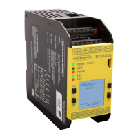
XS26-2 and SC26-2 Base Safety Controller Modules
Power
24 V dc ± 20% (incl. ripple), 100 mA no load
Ethernet models: add 40 mA
Display models: add 20 mA
Expandable models: 3.6 A max. bus load
Network Interface (Ethernet models only)
Ethernet 10/100 Base-T/TX, RJ45 modular connector
Selectable auto negotiate or manual rate and duplex
Auto MDI/MDIX (auto cross)
Protocols: EtherNet/IP (with PCCC), Modbus/TCP, and
PROFINET (FID 2 only)
Data: 64 configurable virtual Status Outputs on FID 1 Base
Controllers or 256 virtual Status Outputs on FID 2 Base
Controllers; fault diagnostic codes and messages; access to
fault log
Convertible I/O
Sourcing current: 80 mA maximum (overcurrent protected)
Automatic Terminal Optimization Feature
Up to two devices
Test Pulse
Width: 200 μs max.
Rate: 200 ms typical
Output Protection
All solid-state outputs (safety and non-safety) are protected from
shorts to 0 V or +24 V, including overcurrent conditions
Safety Ratings
PFH [1/h]: 1.05 × 10
-9
Proof Test Interval: 20 years
Certifications
Programmable
Safety
Controller
3NBN
Safety Inputs (and Convertible I/O when used as inputs)
Input On threshold: > 15 V dc (guaranteed on), 30 V dc max.
Input Off threshold: < 5 V dc and < 2 mA, –3 V dc min.
Input On current: 5 mA typical at 24 V dc, 50 mA peak contact cleaning current
at 24 V dc
Input lead resistance: 300 Ω max. (150 Ω per lead)
Input requirements for a 4-wire Safety Mat:
· Max. capacity between plates: 0.22 μF
· Max. capacity between bottom plate and ground: 0.22 μF
· Max. resistance between the 2 input terminals of one plate: 20 Ω
Solid State Safety Outputs
0.5 A max. at 24 V dc (1.0 V dc max. drop), 1 A max. inrush
Output OFF threshold: 1.7 V dc typical (2.0 V dc max.)
Output leakage current: 50 μA max. with open 0 V
Load: 0.1 μF max., 1 H max., 10 Ω max. per lead
Response and Recovery Times
Input to Output Response Time (Input Stop to Output Off): see the
Configuration Summary in the Software, as it can vary
Input Recovery Time (Stop to Run): 250 ms typical, 400 ms max.
Output xA to Output xB turn On differential (used as a pair, not split): 6 to 14
ms typical, ±25 ms max.
Output X to Output Y turn on Differential (same input, same delay, any module):
3 scan times +25 ms max.
Virtual Input (Mute Enable and On/Off) Timing (FID 2 only): RPI + 200 ms typical
Virtual Input (Manual Reset and Cancel Delay) Timing (FID 2 only): see
Virtual
Non-Safety Input Devices (XS/SC26-2 FID 2 Only and SC10-2)
on page 44 for
details
Delay Tolerance
±(0.02% + 2 scan times)
XS/SC26-2 and SC10-2 Safety Controllers
16 www.bannerengineering.com - Tel: + 1 888 373 6767
 Loading...
