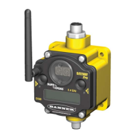
device has allocated Node registers 7, 15, and 16 that send preset data to the event counter. When power is applied to the Node, the
counter value is reset to the last saved value. The counter value is saved every hour.
Setting the counter using the preset or clear functions saves the preset value or zeroes in EEPROM.
Host Control Counter Preset
The event counter input is a 32-bit value that can be preset using the parameter control codes 143 (0x8F) and 144 (0x90). Parameter
control code 143 writes the lower half [15:0] of the counter and code 144 writes the upper half [31:16] of the counter.
Select which counter to preset by defining the Counter Select Mask. The first bit position of the mask (bit 0, right justified) selects the first
counter and the second bit position selected the second counter. Set the Node’s register 16 to the high or low data value. Read Node
register 7 for the transfer acknowledgement. Write to Node register 16 before writing to Node register 15.
There are 16 Modbus holding registers for each SureCross™ device. To calculate the registers for other Nodes, use this equation: Reg-
ister number = I/O# + (Node # × 16). For example, the Gateway is always device 0 (or Node 0), so the Gateway’s holding registers are
registers 1 through 16. The registers for Node 1 are 17 through 32 and the registers for Node 2 are 33 through 48.
Node Reg 16 Low or High Value
Node Reg 15 143 or 144 (0x8F or 0x90) Counter Select Mask
Node Reg 7 Acknowledge Code 143 or 144 Acknowledge Counter Select Mask
Example: To preset Node 2’s counter 2 to the value 20,567,001 (hex 0139 D3D9), follow these steps:
1. Write the upper word to the counter using control code 144 (0x90).
Node Reg 48 0139
Node Reg 47 0x90 2
Node Reg 39 0x90 2
2. Write the lower word to the counter using control code 143 (0x8F).
Node Reg 48 D3D9
Node Reg 47 0x8F 2
Node Reg 39 0x8F 2
The counter has been preset to 20,567,001 (0x0139 D3D9)
Preset Using the Node’s Menu System
To manually enter a counter preset, follow the LCD menu flow using the diagram shown.
1. Single click button 1 to move across the top level menus. Click button 1 until the display shows IOCFG.
2. Click button 2 to enter the I/O Configuration submenu structure.
3. Single click button 1 to move across the I/O points. Single click button 2 to enter the preset configuration for the desired I/O point. I/
O 3 is the event counter and I/O 5 is the rate counter.
4. The screen displays the counter number, usually CNTR 1 or CNTR 2. Single click button 2 to move down the menu structure.
5. Use the right rotary switch to begin setting the counter preset. Digit selection begins with the least significant digit (the right-most
digit). After selecting the least significant digit of the counter preset, single click button 1 to advance left to the next significant digit.
6. Use the right rotary switch to select the second digit. Single click button 1 to advance to the next digit.
7. When the counter preset has been entered, single click button 2 to save the value. The second screen of counter preset digits
displays only when more than four digits are necessary. The preset counter may be set from zero to 4,000,000,000.
8. Double click button 2 to exit this menu. If you try to leave this menu without resetting the rotary switch back to its network address
position, the menu system prompts you to correct the switch setting before returning to RUN mode. The prior network address
setting displays.
9. Single click button 2 to enter the new network address. The new address is confirmed.
10. Single click button 2 to save the network address and return to the IOCFG menu and RUN mode.
SureCross DX80 FlexPower Node with Counter Inputs
10 www.bannerengineering.com - tel: 763-544-3164 P/N 136348 rev. G

 Loading...