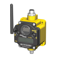
Wiring Diagrams for Counter Inputs
Connecting dc power to the communication pins will cause permanent damage. For the DX8x...C models, PWR in the wiring diagram
refers to V+ on the wiring board and GND in the wiring diagram refers to V- on the wiring board.
Counter Inputs (Sourcing/PNP) Counter Inputs (Sinking/NPN)
CIx
PWR or SPx
Counter
(Sourcing)
SureCross Device
CIx
GND
Counter
(Sinking)
SureCross Device
Additional Information
For additional information, including installation and setup, weatherproofing, device menu maps, troubleshooting, and a list of accesso-
ries, refer to one of the following product manuals
• SureCross Quick Start Guide: Banner part number 128185
• SureCross Wireless I/O Network Manual: 132607
• Web Configurator Manual (used with "Pro" and DX83 models): 134421
Modbus Register Table (Event and Rate Counter)
I/O Modbus Holding Register I/O Type Units I/O Range Holding Register
Representation
Terminal
Block La-
bels
Gateway Any Node Min. Val-
ue
Max.
Value
Min.
(Dec.)
Max.
(Dec.)
1 1 1 + (Node# × 16) Discrete IN 1 - 0 1 0 1 DI1
2 2 2 + (Node# × 16) Discrete IN 2 - 0 1 0 1 DI2
3 3 3 + (Node# × 16) Event Count 1
(high)**
- 0 65535 0 65535
CI1
4 4 4 + (Node# × 16) Event Count 1
(low)**
- 0 65535 0 65535
5 5 5 + (Node# × 16) Rate Count Hz 0 65535 0 65535 CI2
6 6 6 + (Node# × 16)
7 7 7 + (Node# × 16) Reserved
8 8 8 + (Node# × 16) Device Message
9 9 9 + (Node# × 16) Discrete OUT 1 - 0 1 0 1 DO1
10 10 10 + (Node# × 16) Discrete OUT 2 - 0 1 0 1 DO2
11 11 11 + (Node# × 16) Clear Counter 1 - 0 1 0 1
12 12 12 + (Node# × 16)
13 13 13 + (Node# × 16) Clear Counter 2 - 0 1 0 1
14 14 14 + (Node# × 16)
15 15 15 + (Node# × 16) Control Message
16 16 16 + (Node# × 16) Reserved
SureCross DX80 FlexPower Node with Counter Inputs
P/N 136348 rev. G www.bannerengineering.com - tel: 763-544-3164 5

 Loading...