Terminal Block (IP20 Housing)
For the DX8x...C models, PWR in the wiring diagram refers to V+ on the wiring board and GND in the wiring diagram refers to V- on the
wiring board. Ignore alternate labeling referring to other models that use this board.
DI1
DI2
DI3
DI4
CMA
CMB
V+
V−
V−
DO1
DO2
DO3
DO4
SP1
SP2
TX/+
RX/−
B+
TIP
TIN
TX2
RX2
CI1
CI2
AXP
AXN
B+. 3.6 to 5.5V dc (for battery powered models only).
CIx. Counter IN x.
DIx. Discrete IN x.
DOx. Discrete OUT x.
RX/-. Serial comms line
SPx. Switch Power. Provides variable power sources for external
devices.
TIN, TIP. Not used. Do not make any wiring connections to these
terminals.
TX/+. Serial comms line
V+. Power, 10 to 30V dc power connection.
V-. Ground/dc common connection.
AXN, AXP. Not used. Do not make any wiring connections to these
terminals.
CMx. Not used. Do not make any wiring connections to these ter-
minals.
Wiring Diagrams for Discrete Inputs
Connecting dc power to the communication pins will cause permanent damage. For the DX8x...C models, PWR in the wiring diagram
refers to V+ on the wiring board and GND in the wiring diagram refers to V- on the wiring board.
Discrete Input Wiring (PNP) Discrete Input Wiring (NPN)
DIx
PWR or SPx
SureCross Device
Wiring Diagrams for Discrete Outputs
Connecting dc power to the communication pins will cause permanent damage. For the DX8x...C models, PWR in the wiring diagram
refers to V+ on the wiring board and GND in the wiring diagram refers to V- on the wiring board.
Discrete Output Wiring (NPN or NMOS)
DOx
PWR or SPx
SureCross Device
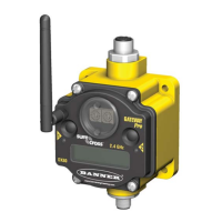
SureCross DX80 FlexPower Node with Counter Inputs
4 www.bannerengineering.com - tel: 763-544-3164 P/N 136348 rev. G
 Loading...
