7.1.1 Control valve
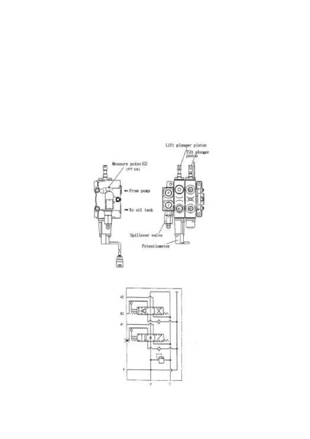
The control valve consists of four valve housings, two spools and one relief valve.
The control valve lever distributes the hydraulic oil from oil pump to lift cylinder or tilt
cylinder. In the control valve, there is relief valve and self-locking valve. The relief valve
installed upon control valve inlet can control the pressure of system, and the self-locking
valve set on the tilting valve pieces is used for preventing serious results’ happening of
tilting cylinder because of misoperation when there is no pressure source. The retaining
valve is separately installed between inlet and lift valve inlet port, and between lift valve
inlet port and tilt valve inlet port. The diagram of control valve is referred to Fig. 7.1.
Fig.7-1 Diagram of control valve