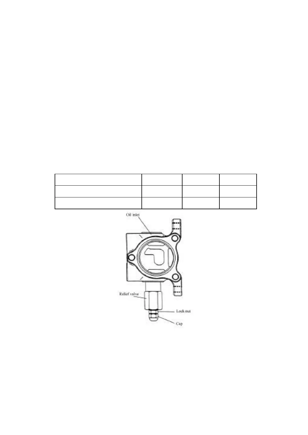
(2) Setting pressure of the relief valve (Fig7-3)
The pressure of the relief valve has been set before delivery. Don’t adjust the
pressure at will, for it will bring danger for system and safety. If the oil pressure is different
with standard value as the following form, according to the measure method specified in
JB/T3300, specialized servicemen adjust the pressure as follows:
(a) Screw out the measured hole plug from the inlet port of control valve and install
the oil-pressure gauge (20MPa) on it.
(b) Operate the tilt lever, measure the pressure when the stroke is to the bottom.
(c) When the oil pressure is different from the specified value, loosen the lock nut of
the surplus valve, adjust the adjusting screw left and right to achieve the specified value.
Turn the screw left when pressure is high, and turn right when it is low.
(d) After having adjusted, tighten up the lock nut.
Fig.7-3 Setting pressure of relief valve
7.1.2 Lift cylinder
The lift cylinder is of single-action piston type. It consists of cylinder body, piston rod,
piston and cylinder head. The bottom of the cylinder is connected with the cylinder
supporter of the outer mast by bolts and pins, while its top (i.e. piston rod head) is
connected with the upper beam of the inner mast.
Pressure of steering unit