back to the reserve tank through the return port until primary cup blocks up the return port.
After the primary cup passes through the return port, the brake fluid in the cylinder is
pressurized and opens the check valve, flowing through the brake pipeline to the
operating cylinder. Thus, each operating cylinder piston is forced outwards. This brings
the friction pieces on the brake shoes come into contact with the brake drum and slows or
stops the truck. Meanwhile, the back cavity of the piston is filled with brake fluid led
through the return port and inlet port. When the brake pedal is released, the piston is
forced back by the return spring. At the same time, the brake fluid in each operating
cylinder is pressurized by the return spring, returning into the master cylinder through the
check valve. With the piston in its original position, the brake fluid in the master cylinder
flows into the reserve tank through the return port. The brake fluid in the brake pipelines
and operating master has a residual pressure proportioned to the set pressure of the
check valve, which makes each operating cylinder piston cup securely seated to prevent
oil leakage and eliminates a possibility of air locking when the truck is sharply braked.
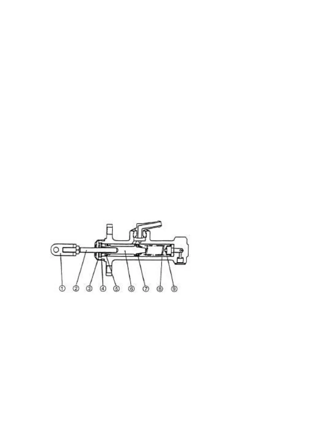
1. Link rod
2. Push rod
3. Dust cover
4. Snap ring
5. Secondary cup
6. Piston
7. Primary cup
8. Spring
9. Check valve
Fig.2-2 Master cylinder
2.1.3 Wheel brake
Mounted on each side of the drive axle, the wheel brake is the internal expansion
hydraulic type consisting of two brake shoes, operating cylinder and adjuster.
The brake shoe, one end of it being connected to the anchor pin and the other to the
adjuster, is stressed on parking brake plate by the spring and spring pull rod. The primary
shoe is provided with the parking pull rod while the secondary shoe with the adjuster lever
of the clearance self-adjuster. See Fig2-3, 2-4, 2-5.