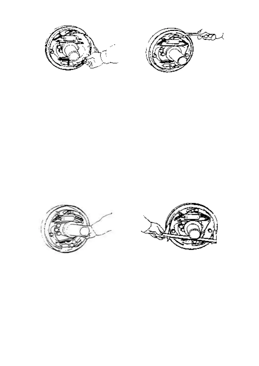
Fig. 2-23 Fig. 2-24
(9) Install the adjuster, adjuster spring, push rod and its return spring.
Pay attention to the following points:
(a) Thread direction of the adjuster and its mounting direction.
(b) Adjuster spring direction (Do not allow the adjuster gear teeth to contact with the
spring).
(c) Return spring direction of the push rod: Spring hook at anchor pin side should be
located at the opposite side to push rod.
(d) Make sure that the adjusting lever lower end is in contact with the adjuster gear
teeth.
(10) Install the brake line on the operating cylinder.
(11) Measure the inner and outer diameter of brake drum. Adjust the adjuster to obtain the
difference needed between the drum inner diameter and the friction piece outer diameter.
Specified difference: 1mm.
Fig. 2-25 Fig. 2-26
2.2.4 Operation test of clearance self-adjuster
(1) Make the brake shoe diameter approach the specified mounting size, and pull the
adjusting level with your finger along the arrow marks as shown in Fig.2-27 to turn the
adjuster gear. When removing off your finger, the adjusting lever should return to its
original position without rotation of the adjuster gear.
Note: Even if the adjuster gear turns back along the adjusting lever motion
when removing your finger, the adjuster will still operate normally after it is fit in the
truck.