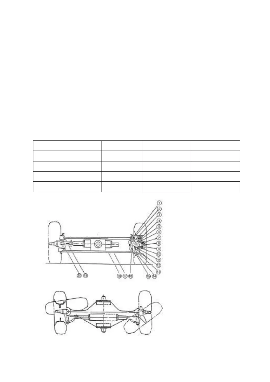
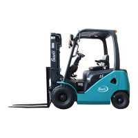
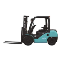
3.1.3 Steering axle
The steering axle is of section-boxed welded construction type (Fig.3-3). It includes
axle body, steering cylinder, link lever, steering knuckle and steering wheel. The steering
axle is of slider crank mechanism. The cylinder piston rod pushes knuckle steering
through link lever, causing wheel’s deflection and truck’s steering. The steering axle is
pivoted in the bearing seats bolted to the rear frame, thus causing the axle body be able
to oscillate around the axles. Left and right knuckles are positioned at two sides of the
steering axle respectively. The rear wheel hubs are fitted to the knuckle shafts through
tapered roll bearings with oil seals keeping the grease in the chambers of the hubs and
the knuckles. The wheels with rims are bolted on the hubs.
The steering tyre, rim and the pressure of the steering wheel:
Fig.3-3 Steering axle
Pressure of steering unit
1. Oil seal
2. Needle bearing
3. Thrust bearing
4. Oil seal
5. Hub nut
6. Tapered roll bearing
7. Tapered roll bearing
8. Lock nut
9. Hub cap
10. Steering hub
11. Lock pin
12. Adjust shim
13. Needle bearing
14. Oil seal
15. King pin
16. Knuckle
17. Steering cylinder
18. Steering axle body
19. Pin shaft
20. Pin shaft