Manual 2100-746D
Page 2 of 59
General Information ......................................................... 4
Shipping Damage ......................................................4
General ..................................................................... 4
Theory of Operation .................................................... 4
Controller Certications ..............................................4
Getting Other Information and Publications ..................4
Control System ............................................................
5
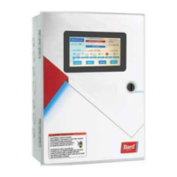
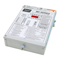
Controller and Accessories ...................................5
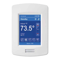
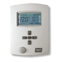
Optional Sensors .......................................... 5
Installation
......................................................................... 6
MC5000 Series Controller ..........................................7
Mounting the MC5000 Series Controller ...............7
Installing Remote Temperature Sensor(s) ..............8
Engineered Features
......................................................... 9
Touch Screen ............................................................9
Main Control Board (MC5300 and MC5600) ..............10
Secondary Control Board (MC5600 Only) ...................11
Main Alarm Board (MC5300-BC and MC5600-BC) .....12
Secondary Alarm Board (MC5600-BC Only) ...............13
Setup
.................................................................................. 14
Guided Setup ..........................................................14
MC5000 Equipment Setup Menu Descriptions ....14
MC5000 Controller System Setup Menu
Descriptions .....................................................14
Equipment Setup Menu............................................14
System Setup Menu .................................................15
Date/Time Setup Menu .............................................15
Comfort Mode .........................................................15
System Status .........................................................15
Cooling Set Points ...................................................15
Heating Set Points ...................................................15
Comfort Mode Cooling Set Points ..............................15
Comfort Mode Heating Set Points .............................. 16
Dehumidication Level Set Points .............................16
Humidication Level Set Points ................................16
Cooling Interstage Differential Set Points ...................16
Cooling Stage Off Differential Set Points ....................16
Heating Interstage Differential Set Points ................... 16
Heating Stage Off Differential Set Points ...................16
Dehumidication Interstage Differential Set Points .....16
Dehumidication Stage Off Differential Set Points ......16
Humidication Interstage Differential Set Points ......... 17
Humidication Stage Off Differential Set Points .........17
High Humidity Alarm Set Points ................................ 17
Low Humidity Alarm Set Points .................................17
Low Temperature Alarm Level Set Points ....................17
High Temperature Alarm Level 1 Set Points ................17
High Temperature Alarm Level 2 Set Points ................17
Heat Pump Lockout Range Set Points ........................ 17
Operation
.......................................................................... 18
Basic Controller Specications/Features .....................18
Temperature Sensors ................................................18
Temperature Sensor Logic ..................................18
Basic Controller Input/Output Specications ..............19
Alarm Board Specications/Features .......................... 19
MC5000 Alarm Board I/O ..................................19
Alarm Board Contacts .................................19
MC5000B w/Enhanced Version Alarm Board
plus MC5000A Inputs/Outputs ...........................20
Low Voltage Field Wiring...........................................20
Controller Grounding ................................................20
Controller Power-Up .................................................20
Emergency Off ......................................................... 20
Staging Delay Periods ..............................................20
Blower Operation .....................................................20
Pre-Purge ................................................................ 20
Pre-Purge Setup ...............................................20
CONTENTS
Pre-Purge Sequence of Operation .......................20
Lead/Lag (Rotation) .................................................21
Cooling Sequence of Operation .................................21
Heating Sequence of Operation .................................21
Electric Heat ....................................................21
Heat Pumps .....................................................21
Humidity Control Option ...........................................24
Dehumidication Sequence ...............................24
Mechanical Sequence ................................24
Synchronized Sequence ..............................25
Humidication Operation ................................... 25
Staging ...................................................................25
Staging Sequence .............................................25
Heating Staging ................................................26
Cooling Staging ................................................26
Adjustable Interstage Differential ................26
Adjustable Off Differential ..........................26
Cooling with Economizer ...................................26
The Advantages of Twinning: Pairs ...............27
The Advantages of Twinning: Triples ............27
Humidication/Dehumidication Demand Staging ..
28
Alternating/Non-Alternating Set Up............................28
Alternating/Non-Alternating Logic .......................28
Alternating ................................................28
Non-Alternating .........................................28
Twinning: Simultaneous Unit Operation ..............30
Triples: Simultaneous Unit Operation ..................31
Alarm Functionality .................................................. 32
Test Mode ...............................................................34
Self Test ..........................................................34
Manual Test .....................................................34
Network/Remote Connectivity .................................... 34
Remote Connectivity .........................................34
Setup ..............................................................34
Touch Screen Display IP Conguration .........34
Webpage IP Conguration ...........................35
Webpages ........................................................36
Navigational Side Pane ...............................36
Modbus ...........................................................37
Connections Diagrams
.................................................. 42
Troubleshooting
.............................................................. 55
Checking Remote (8408-061) or Local Temperature/
humidity Sensor (8408-059)
....................................55
Checking Remote Temperature Sensor 8301-095 .......56
Troubleshooting Alarms ............................................57
MC5000 Replacement Parts List
................................... 59
FIGURES AND TABLES
Figure 1
Typical MC5000 Component Location ............
6
Figure 2
MC5000 Controller Dimensional Drawing
........7
Figure 3 Controller Grounding Lugs ...........................8
Figure 4 Optional Remote Temperature Sensor
Installation ................................................8
Figure 5 MC5000 Series Touch Screen Interface ........9
Figure 6
Mechanical Dehumidication ....................
24
Figure 7 Synchronized Dehumidication .................. 25
Figure 8 Heating Staging .......................................26
Figure 9 Cooling with Six Single Stage Units
(w/Economizers) .......................................26
Figure 10 Cooling with Six Single Stage Units
(w/Economizers) Using Twinning/
Pairs Option ............................................. 27
Figure 11 Cooling with Six Single Stage Units
(w/Economizers) Using Twinning/
Triples Option ..........................................27
Figure 12 Alternating Sequence Cooling ....................29
Figure 13 Non-Alternating Sequence Cooling .............29
 Loading...