Manual 2100-746D
Page 45 of 59
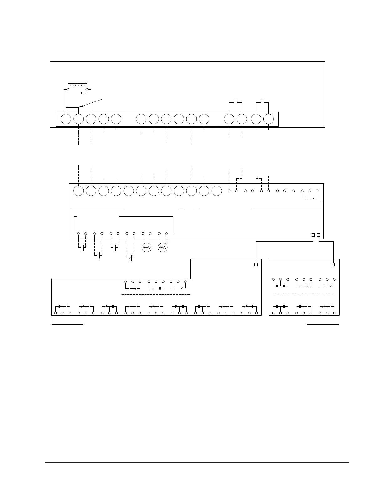
MC-5300: SYSTEM 1-3 OR MC-5600: SYSTEM 1-6
LOCKOUT 5LOCKOUT 6 LOCKOUT 4
POWER
LOSS 6
POWER
LOSS 5
POWER
LOSS 4
HIGH
TEMP 2
NOTE: NOT ALL TERMINALS
REPRESENTED FOR ALARM
BOARD 1
LOCKOUT 1LOCKOUT 3 LOCKOUT 2
POWER
LOSS 3
POWER
LOSS 2
LOW
TEMP
HIGH
TEMP 1
POWER
LOSS 1 VENTFILTERTHEFT
ALARM BOARD 1
MC5300-BC AND MC5600-BC
ALARM BOARD 2
MC5600-BC ONLY
Stage 1 Electric Heat
Theft
Generator
Contacts
Emergency
Off Contacts
Optional Remote
Sensors #1 and #2
Contacts
(opt.)
Filter
Switch
Stage 1 Cooling
7.) MC5300-BC and MC5600-BC controllers have additional alarm board(s) with dry contacts for wired alarms.
PRIMARY BOARD
REM 2REM 1
control board with connections for units 4 to 6.
OFFGENVENTTHEFT
EMERG
6.) All MC controllers will have a primary control board with connections for units 1 to 3. MC5600 controllers only will have an additional secondary
Factory Jumper
R C W1 W2 EC Y1 Y2 G O/B A D H
FILTER DUST LOR AUX IN EIN
NO C NC
AUX OUT
DA
W3
GY2Y1
(opt.)
W2CR
11 12 2 3
RT
Shutdown
Emergency
MC5600 PRIMARY AND SECONDARY BOARD.
W**A/W**L SERIES UNIT
24VAC
Common
AVAILABLE NOC REMOTE MONITORING DRY CONTACTS. MC5300-BC AND MC5600-BC ONLY.
Stage 2 Electric Heat
Indoor Fan
M. Dehumidification
Filter Switch
Filter Switch
Compressor Lockout
Compressor Lockout
MC5300 PRIMARY BOARD ONLY.
TERMINAL STRIP
24VAC
W**A/W**L SERIES UNIT WITH ECONOMIZER
Ventilation
LOW VOLTAGE
MC SERIES CONTROL BOARDS
(Optional)
Relay
Alarm
(Optional)
MIS-4197 B
Stage 2 Cooling
Notes:
1.) Stage 2 Electric Heat, Ventilation, Mechanical Dehumidification, and Filter Switch are optional components. Refer to model nomenclature to
verify optional equipment installed in unit.
2.) Ventilation wire between "A" terminals allows for ventilation during a HIGH TEMP 2 alarm. Make sure to set min. position in WA series unit
economizer JADE controller to 10V (fully open) to allow ventilation during a HIGH TEMP 2 alarm.
3.) Optional remote sensors #1 and #2 are temperature resistance 10k type 2. Remote sensor #2 can be used as an outdoor or indoor sensor.
4.) Emergency Off Contacts used in MC series controller to shut down all units. Emergency shutdo
wn fac
tory jumper may be removed to field
install a normally closed relay at each individual unit.
5.) Units with economizers do not have a Balanced Climate factory installed brass jumper between Y1 and Y2. Please refer to vent manuals for
instruction on how Balanced Climate works with each vent.
Vent
Contacts
B/W1
FIGURE 21
W**A/W**L Series Unit with Economizer