Manual 2100-342
I
Page 22 of 24
REMOVAL OF FAN SHROUD
1. Disconnect all power to the unit.
2. Remove the screws holding both grilles, one on each
side of unit, and remove grilles.
3. Remove screws holding fan shroud to condenser and
bottom. Nine (9) screws.
4. Unwire condenser fan motor.
5. Slide complete motor, fan blade, and shroud
assembly out the left side of the unit.
6. Service motor/fan as needed.
7. Reverse steps to reinstall.
REFRIGERANT CHARGE
The correct system R-22 charge is shown on the unit
rating plate. Optimum unit performance will occur with
a refrigerant charge resulting in a suction line
temperature (6" from compressor) as shown in Table 7.
The suction line temperatures in Table 7 are based upon
80° F dry bulb / 67° F wet bulb (50% R.H.) temperature
and rated airflow across the evaporator during cooling
cycle.
ledoM
detaR
wolfriA
DO59
erutarepmeT
DO28
erutarepmeT
183HW
134HW
194HW
0011
0031
0521
37-17
57-27
07-86
07-86
17-96
66-46
TABLE 7
REFRIGERANT CHARGE
ledoM
noisnemiD
A
183HW
134HW
194HW
00.1
ledoM183HW
134HW
194HW
WK
hgiH
deepS
deM
deepS
woL
deepS
hgiH
deepS
deM
deepS
50A-3.03.03.03.03.0
80A-3.03.03.04.04.0
01A-3.03.02.03.03.0
60B-4.03.03.03.03.0
90B-4.03.03.03.03.0
60C-3.03.03.03.03.0
90C-3.03.03.03.03.0
TABLE 9
MAXIMUM ESP OF OPERATION
ELECTRIC HEAT ONLY
Values shown are for units equipped with standard 1-inch
throwaway filter or 1-inch washable filter. Derate ESP by .15
for 2-inch pleated filters.
TABLE 8
RECOMMENDED OPERATING RANGES
* Rated CFM and ESP on high speed tap.
ledoM
detaR
*MFC
detaR
*PSE
dednemmoceR
egnaRwolfriA
183HW001151.058–0521
134HW003151.058–5741
194HW052102.058–5741
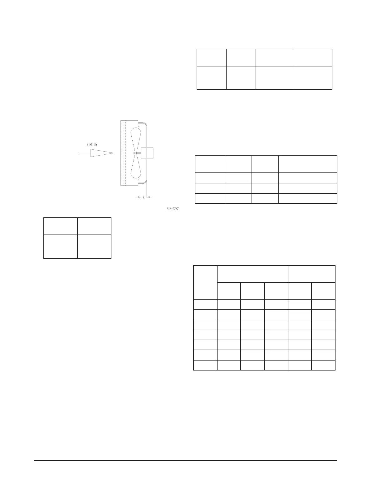
FIGURE 15
FAN BLADE SETTING
FAN BLADE SETTING DIMENSIONS
Shown in Figure 15 are the correct fan blade setting
dimensions for proper air delivery across the outdoor
coil.
Any service work requiring removal or adjustment in
the fan and/or motor area will require that the
dimensions below be checked and blade adjusted in or
out on the motor shaft accordingly.
TABLE 6
FAN BLADE SETTING
DIMENSION