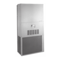
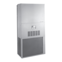
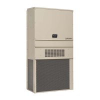
This document provides installation and operational instructions for Bard Wall Mounted Package Heat Pumps, specifically models WH381, WH431, and WH491. These units are self-contained, air-cooled heat pumps designed for use with or without ductwork, offering both heating and cooling functionalities.
Function Description
The Bard Wall Mounted Package Heat Pumps are designed to provide climate control for residential and commercial applications. They operate as heat pumps, offering efficient heating and cooling by transferring heat rather than generating it. The units are fully assembled and charged with refrigerant from the factory, with all internal wiring completed. They are suitable for various wall constructions, including wood frame and concrete block, provided the wall is strong enough to support the unit's weight and prevent vibration.
Key operational features include:
- Cooling Cycle: Initiated by a thermostat call, engaging the compressor and outdoor motor. The indoor blower motor also starts automatically or can be manually engaged for continuous air circulation.
- Heating Cycle: Controlled by a 24V solenoid coil on the reversing valve. Depending on the thermostat option, the system can automatically change over between heating and cooling or maintain continuous heating operation, energizing the reversing valve solenoid whenever the system switch is in the "Heat" position.
- Defrost Cycle: Managed by a solid-state heat pump control based on temperature and time. When the outdoor coil temperature drops to 30°F or below, a sensor signals the control, initiating a defrost timer. After a set time (typically 60 minutes), the system switches to cooling mode, stops the outdoor motor, energizes electric heaters, and melts accumulated frost. The system returns to heating operations automatically when the coil temperature reaches approximately 57°F or after 10 minutes in case of prolonged defrost.
- Electric Heat Hold-Off: An optional feature that disables electric heat operation until outdoor temperatures reach a certain design point. This maximizes efficiency by prioritizing heat pump operation for space temperature recovery, especially after setback conditions or thermostat adjustments.
Important Technical Specifications
The manual provides detailed specifications across various tables:
Model Nomenclature (Page 4):
- Models: WH381 (3 Ton), WH431 (3.5 Ton), WH491 (4 Ton).
- Voltage & Phase: A (230/208V/60Hz/1 Phase), B (230/208V/60Hz/3 Phase), C (460V/60Hz/3 Phase).
- KW Options: Available in various KW ratings (e.g., 5, 6, 8, 9, 10 KW) with corresponding BTU and amperage values for different voltages and phases. For example, a WH381-A with 5 KW electric heat at 240-1V draws 20.8A and provides 17065 BTU.
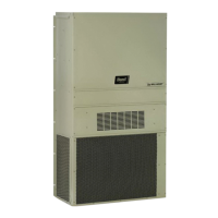
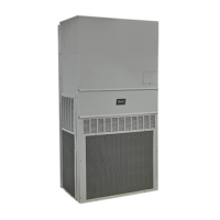
- Color Options: Standard Beige, Buckeye Gray.
- Ventilation Options: Barometric Fresh Air Damper (Standard), Blank-off Plate, Commercial Ventilator (Motorized w/o Exhaust), Motorized Fresh Air Damper, Adjustable Fresh Air Damper.
- Filter Options: 1-Inch Throwaway (Standard), 1-Inch Washable, 2-Inch Pleated.
- Coil Options: Standard, Phenolic Coated Evaporator, Phenolic Coated Condenser, Phenolic Coated Evaporator and Condenser.
- Outlet Options: Front (Standard).
Unit Dimensions (Figure 1, Page 5):
- Width (W): 42.075 inches
- Depth (D): 22.432 inches
- Height (H): 84.875 inches
- Supply Air Opening: 9.88 x 29.88 inches
- Return Air Opening: 15.88 x 29.88 inches
Electrical Specifications (Table 2, Page 6):
- Minimum Circuit Ampacity (MCA): Varies by model and KW. For example, WH381-A00 (single circuit) has an MCA of 31A, while WH381-A05 (dual circuit) has MCAs of 31A and 26A.
- Maximum External Fuse or Circuit Breaker (MOCP): Varies by model and KW. For example, WH381-A00 (single circuit) has an MOCP of 45A, while WH381-A05 (dual circuit) has MOCPs of 50A and 30A.
- Field Power Wire Size: Recommended wire sizes (e.g., 8, 6, 4 gauge) and ground wire sizes (e.g., 10, 8 gauge) are provided, based on 75°C copper wire and conforming to NEC and local codes.
- Transformer Voltage Taps: Units are factory-wired on 240V tap. For 208V operation, reconnection is required. Acceptable operating voltage ranges are 253-216V for 240V tap and 220-187V for 208V tap.
Thermostat Wire Size (Table 3, Page 15):
- Provides recommended wire gauges (20, 18, 16, 14, 12 gauge) and maximum distances in feet for 55 VA transformers.
Refrigerant Charge (Table 7, Page 22):
- Indicates suction line temperatures for optimal performance based on rated airflow and outdoor temperatures (e.g., WH381 at 1100 CFM: 71-73°F suction line at 95°F OD, 68-70°F at 82°F OD).
Recommended Operating Ranges (Table 8, Page 22):
- Rated CFM: WH381 (1100), WH431 (1300), WH491 (1250).
- Rated ESP: WH381 (0.15), WH431 (0.15), WH491 (0.20).
- Recommended Airflow Range: WH381 (850-1250), WH431 (850-1475), WH491 (850-1475).
Maximum ESP of Operation (Electric Heat Only) (Table 9, Page 22):
- Provides maximum external static pressure (ESP) values for different KW electric heat options and fan speeds (High, Med, Low). For example, WH381-A05 has a maximum ESP of 0.3 at all speeds.
Indoor Blower Performance (Table 10, Page 23):
- Lists CFM values at different ESPs for dry and wet coil conditions across high, medium, and low fan speeds for WH381, WH431, and WH491 models. For example, WH381 at 0.0 ESP provides 1625 CFM (dry coil) on high speed.
Pressure Tables (Tables 11 & 12, Page 24):
- Cooling: Provides low and high side pressures (PSIG) based on return air temperature (DB/WB) and outdoor coil temperature.
- Heating: Provides low and high side pressures (PSIG) based on return air temperature and outdoor coil temperature.
Usage Features
- Ductwork Flexibility: Designed for use with or without ductwork. Flanges are provided for easy attachment of supply and return ducts.
- Fresh Air Intake: Units come with punched fresh air inlet slots. Optional fresh air damper assemblies are available, with adjustable maximum and minimum blade position stops. A blank-off plate is recommended for maximum energy efficiency.
- Condensate Drains: Includes a plastic drain hose for the evaporator and a hole in the unit base for an optional condenser drain connection kit (8620-160). Both systems require an open or vented drain to ensure proper drainage.
- Filters: Supplied with a 1-inch throwaway filter, serviceable from the outside. Optional 1-inch washable and 2-inch pleated filters are available, with adjustable internal filter brackets.
- Low Voltage Wiring: Units feature a 24V terminal board for thermostat connections. A 9-conductor, 18-gauge copper color-coded thermostat cable is recommended.
- Three Phase Scroll Compressor Start-Up: For three-phase units, a phase monitor ensures proper rotation direction. If phases are reversed, a red fault LED will illuminate, and compressor operation will be inhibited. Correct rotation is verified by observing suction pressure drops and discharge pressure rises when the compressor is energized.
- High Pressure Switch: All models include a remote reset high-pressure switch that can be reset by cycling the thermostat off and on.
- Two-Speed Outdoor Fan Motors: All units feature two-speed outdoor fan motors. In cooling mode, the fan operates at low speed below 80°F outdoor temperature and at high speed in heating mode.
- Defrost Control Settings: The heat pump defrost control board offers 30, 60, or 90-minute settings, with units factory-shipped on the 60-minute pin. A cycle speed-up jumper allows for accelerated defrost testing.
Maintenance Features
- Filter Serviceability: The 1-inch throwaway filter can be easily serviced from the outside by removing the service door.
- Outdoor Coil Cleaning: Periodic cleaning of the outdoor coil is essential to maintain full and unrestricted airflow circulation.
- Troubleshooting Guide: A comprehensive troubleshooting table (Table 5, Page 20) helps diagnose common issues such as compressor not starting, outdoor fan motor not running, reversing valve not energizing, and defrost cycle problems. It provides possible causes and steps for checking and repairing.
- Temperature Sensor Check: Instructions are provided for checking the outdoor unit temperature sensor's resistance using an ohmmeter and comparing it to a temperature vs. resistance chart (Page 21) to ensure proper operation.
- Fan Blade Setting: Figure 15 (Page 22) illustrates the correct fan blade setting dimensions, which should be checked and adjusted after any service work involving the fan or motor area.
- Fan Shroud Removal: Detailed steps are provided for removing the fan shroud, motor, and fan blade assembly for service.
- Refrigerant Charge Verification: The manual emphasizes verifying the correct R-22 charge as indicated on the unit rating plate for optimum performance. Pressure tables are provided to assist in this verification. If there is doubt about the charge, it should be removed, the system evacuated, and recharged according to serial plate instructions.
- Crankcase Heaters: WH491-B and -C models are equipped with compressor crankcase heaters, which are on/off heaters controlled by the compressor contactor. These are crucial for preventing compressor damage from liquid refrigerant, especially after power has been removed for 12 hours or longer. Specific start-up procedures are outlined to ensure the heater has evaporated liquid refrigerant before compressor operation.
- Lockable Disconnect Access: The disconnect access door can be locked to prevent unauthorized access. A tab can be bent to align with a slot in the door, allowing a padlock to be placed through the hole.