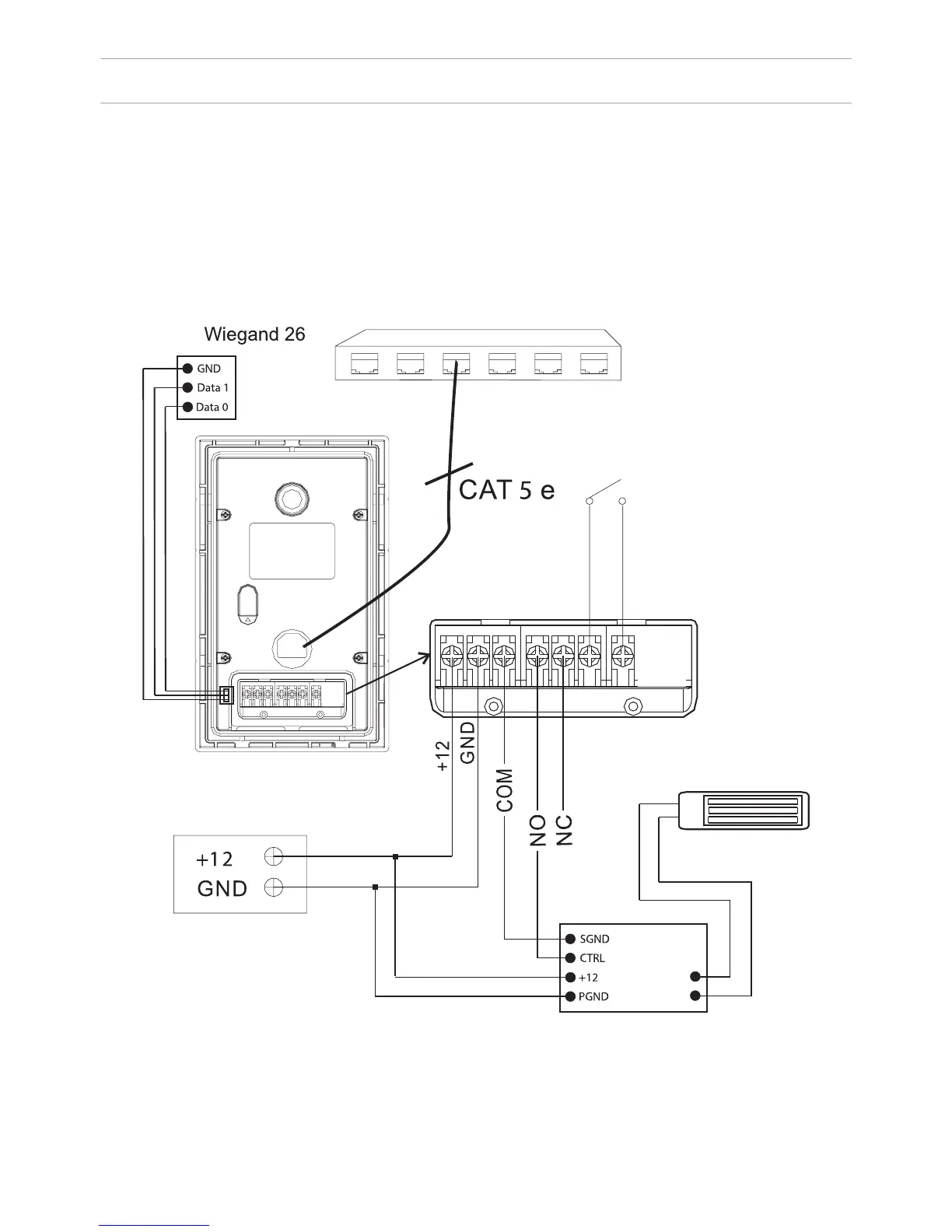
CONNECTION SCHEME
26
Connection using an external power supply.
For connecting high power electric locks, you must use an additional power sup-
ply. The BA-04 and BA-08 connection diagram from the included power supply,
with an electromechanical lock is presented below:
Attention:
The opening time is set by adjusting the
resistor on the delay module board SH-40.
Delay module SH-40
“EXIT“ CONTACT 1
“EXIT“ CONTACT 2
“EXIT“ BUTTON
LOCK
POWER SUPPLY
V
V
Network switch
v