2.2.1.1
INPUT
INTERFACE
The
input
interface
receives the
signals
from
the host system. Table
2-1
lists
and
defines
the input
signals.
The
input
lines
are terminated
by
pull
up
re-
sistors
of
150
Ohm.
In
aserial
configuration
only the
last
drive will contain the pull
up
resistor
network.
The
receivers send the input signals to the
different
parts
of the drive
electronics.
SIGNAL
NAME
DEFINITION
SELECT
Selects the desired
mini
disk
(1-3)
/
drive.
Enables
all
other
interface
lines
except
MOTOR
ON,
WRITE
DATA,
SIDE
SELECT
and
DIRECTION
IN.
WRITE
DATA/
This
line
carries
low
active
pulses representing data to
be
recorded
on
the
mini
disko
__
C_D_-
:~
J L L
~+4~
200
nse
emin
___
:-i
-
20
ns
I
...
8 -00
",sec
- 40
nsec
WRITE
GATE/
Low
input enables recording
of
WRITE
DATA
on
disko
High
input enables reading
from
the Flexy Disk.
MOTOR
ON/
This
line
turns
on
the drive
motor
and
the stepper
motor
and
is
not gated
by
SELECT.
A
recalibrate
operation
must
be
performed
to
obtain correct
head
positioning every time
after
the
MOTOR
ON
signal
goes
active.Switching of the stepper
motor
may
be
disabled
by
remov-
ing a jumper. This avoids
re-
calibrating
after
switching
on
the dri
ve
motor.
DIRECTION
IN/
Defines motion
of
the read/
write head
LOW
= in (towards Track
39)
HIGH
= out
(towards Track
0)
This
line
is
not gated
by
SELECT.
STEP/
Used
in conjunction with
DIREC-
TION
IN
and
causes the read/
write
head
to
be
moved
from
track
to
track.
HEAD
LOAD/
This
line
is
used
to
press the
mini
disk against the read/
write
head
if
the
mini
disk
drive
is
ready.
To
activate
this
line
a jumper
has
to
be
changed.
IN
USE/
This
line
controis the door
lock solenoid.
Also
the
activity
LED
can
be
switched
on.
If
the
IN
USE/
signal
is
used, the disk
change
option
must
be
disabled.
S
IDE
SELECT
/
This
line
defines whether
head
0 or
head
1 of the
mini
disk drive
is
used. A
hi
gh
si gnal
selects
head
0, a
low
signal
selects
head
1. This
line
is
not gated
by
SELECT.
On
BASF
6106
head
1
is
not
installed.
TAßlE
2 - 1
INPUT
SIGNALS
2 - 6
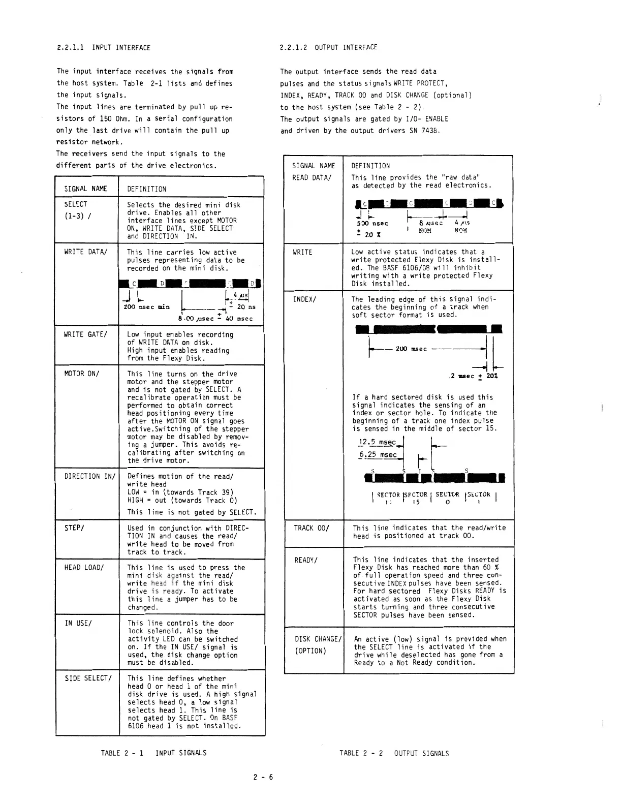
2.2.1.2
OUTPUT
INTERFACE
The
output
interface
sends the read data
pulses
and
the
status
signals
WRlTE
PROTECT,
INDEX,
READY,
TRACK
00
and
DISK
CHANGE
(optional)
to
the host system (see Table 2 - 2).
The
output signals are gated
by
1/0-
ENAßlE
and
driven
by
the output drivers
SN
7438.
SIGNAL
NAME
READ
DATA/
WRITE
INDEX/
TRACK
00/
READY/
DISK
CHANGE!
(OPTION)
DEFINITION
This
line
provides the
"raw
data"
as
detected
by
the read
electronics.
~
__
~~
__
~
__
~~c_1
..!
~
5:)0
nsec
!
2_0
%
low
active
status
indicates
that
a
write protected
F.lexy
Disk
is
install-
ed.
The
BASF
6106/08 will
inhibit
writing with a write protected Flexy
Disk
installed.
The
leading
edge
of
this
signal
indi-
cates the beginning of a track
when
soft
sector
format
is
used.
•
•
1---
200
lUSec
-----j
L
.2
...
ec
!:
20%
If
a hard sectored disk
is
used
this
signal indicates the sensing of
an
index or
sector
hole.
To
indicate the
beginning of a track
one
index pulse
is
sensed in the middle of
sector
15.
_,2.';"",,,
q f.-
~!~5ec
~.
l
"
s.r.
I
,ErTOR
ISFC'OR !
SEC1"(~
I SECrok
" 15 I 0 I I
•
This
line
indicates
that
the read/write
head
is
positioned
at
track 00.
This
line
indicates
that
the inserted
Flexy
Disk
has
reached
more
than
60
%
of·full
operation speed
and
three con-
secutive
INDEX
pulses
have
been
sensed.
For
hard sectored Flexy
Disks
READY
is
activated
as
soon
as
the Flexy
Disk
starts
turning
and
three consecutive
SECTOR
pulses
have
been
sensed.
An
active
(low)
signal
is
provided
when
the
SElECT
line
is
activated
if
the
drive while deselected
has
gone
from
a
Ready
to a
Not
Ready
condition.
TAßlE
2 - 2
OUTPuT
SIGNALS