13-32 9469200995
BESTlogic™Plus DGC-2020ES
Table 13-4. Status Indicators
Logic Save Status
(Left Indicator)
Logic has changed since last save.
Logic has NOT changed since last save.
Logic Diagram Status
(Center Indicator)
Requirements NOT met as listed above.
Requirements met as listed above.
Logic Layer Status
(Right Indicator)
Requirements NOT met as listed above.
Requirements met as listed above.
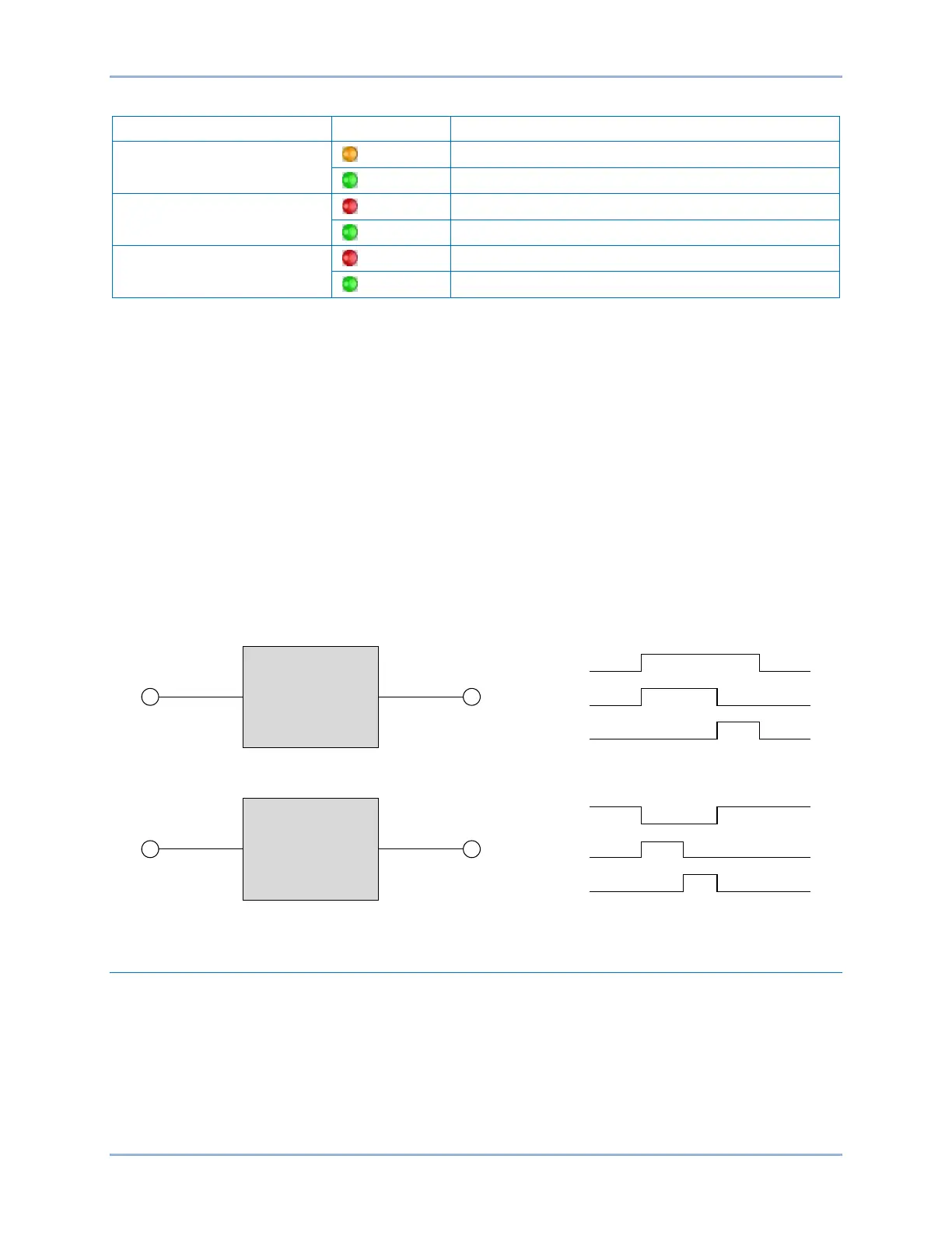
Pickup and Dropout Timers
A pickup timer produces a true output when the elapsed time is greater than or equal to the Pickup Time
setting after a false to true transition occurs on the Initiate input from the connected logic. Whenever the
Initiate input status transitions to false, the output transitions to false immediately.
A drop out timer produces a true output when the elapsed time is greater than or equal to the Dropout
Time setting after a true to false transition occurs on the Initiate input from the connected logic. Whenever
the Initiate input transitions to true, the output transitions to false immediately. Refer to Figure 13-2.
To program logic timer settings, use the Settings Explorer within BESTCOMSPlus to open the
BESTlogicPlus Programmable Logic/Logic Timers tree branch. Enter a Name label that you want to
appear on the timer logic block. The Time Delay value range is 0 to 250 hours in 1 hour increments, 0 to
250 minutes in 1 minute increments, or 0 to 1,800 seconds in 0.1 second increments.
Next, open the Components tab inside the BESTlogicPlus window and drag a timer onto the program
grid. Right click on the timer to select the timer you want to use that was previously set on the Logic
Timers tree branch. The Logic Timer Properties Dialog Box will appear. Select the timer you want to use.
Timing accuracy is ±15 milliseconds.
Figure 13-2. Pickup and Dropout Timer Logic Blocks
Offline Logic Simulator
The offline logic simulator allows you to change the state of various logic elements to illustrate how that
state travels through the system. Before running the logic simulator, you must click the Save button on
the BESTlogicPlus toolbar to save the logic to memory. Changes to the logic (other than changing the
state) are disabled when the simulator is enabled. Colors are selected by clicking the Options button on
the BESTlogicPlus toolbar. By default, Logic 0 is red and Logic 1 is green. Using your mouse, double-
click on a logic element to change its state.
An example of the offline logic simulator is shown in Figure 13-3. Output 1 is Logic 0 (red) when Virtual
Switch 1 is Logic 0 (red) and Fixed 1 is Logic 1 (green).
Initiate
Pickup Time
Output
Initiate
Dropout Time
Output
Pickup
Timer
Dropout
Timer
Output
Output
Initiate
Initiate
P0048-03

 Loading...


