2-1
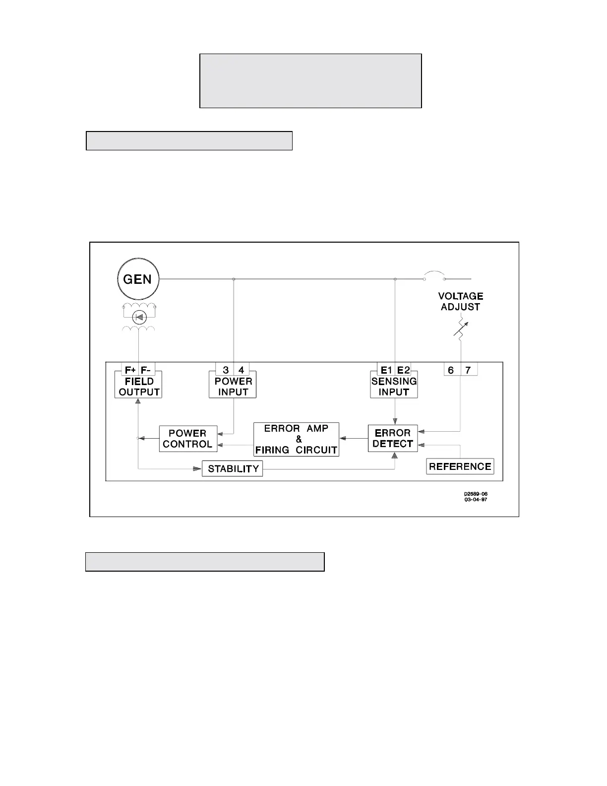
Refer to the Block Diagram, Figure 2-1. The voltage regulator senses the generator voltage, com-
pares a rectified sample of that voltage with a reference diode (zener) voltage and supplies the field
current required to maintain the predetermined ratio between the generator voltage and the
reference voltage. This unit consists of five basic circuits. These are a sensing circuit, an error
detector, an error amplifier, a power controller and a stabilization network.
Figure 2-1. Overall Block Diagram.
a.
Starting large motors or providing fault current for selective breaker tripping
.
(1) For generators equipped with brushless exciters or for static excited generators the field power is
taken from the generator output voltage. A heavy load, such as a large motor, can cause the
generator voltage to decrease substantially at the first few cycles after load applications. A short
circuit on the generator output could reduce the voltage from the generator to zero. Either of these
conditions can cause reduction of the available field power to a level which will not sustain generator
voltage. Accessory excitation support systems are available which take advantage of the generator
line currents as a source of excitation power during either condition.
(2) For brush-type rotation excited generators, the exciter armature connections can be used as an
alternate source of excitation during either of the conditions described above to provide excitation
SECTION 2
PRINCIPLES OF OPERATION
2-1. FUNCTIONAL CIRCUITS
2-2. APPLICATION INFORMATION