5-1
Periodic inspection should be made on this unit to insure it is kept clean and free from dirt and
moisture. Also, it is recommended the connections between the regulator and the system be
checked and tightened at this time.
Due to a protective transparent conformal coating, repair on the printed circuit board is difficult and
should only be attempted by qualified personal. An effective test, used to determine if the regulator
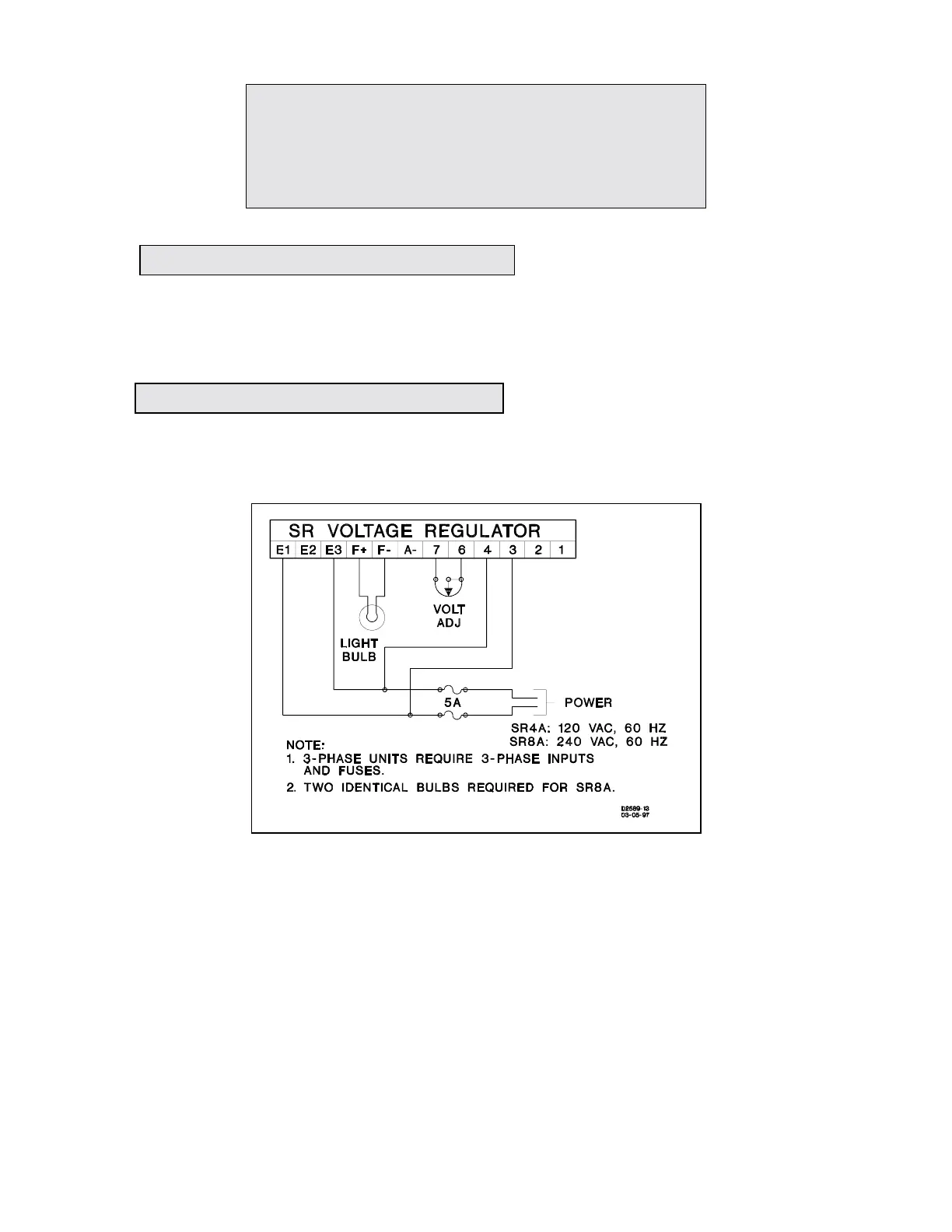
is basically operational, given below. Refer to Figure 5-1.
a. Move the wire on the sensing transformer (T1) to the terminal listed below:
SR4A: Move to 120 V tap.
SR8A: Move to 240 V tap.
b. Adjust the voltage stability potentiometer (R4) fully counter-clockwise (CCW).
c. Connect the voltage regulator as shown in Figure 5-1. The bulb should be 120 V and not more
than 300 W. See Note 1 of the drawing for the SR8A.
d. Adjust the voltage adjust potentiometer for maximum resistance.
e. Connect the regulator to the power source. The bulb should flash on momentarily and then
extinguish.
SECTION 5
MAINTENANCE, REPLACEMENT PARTS,
AND TROUBLESHOOTING
5-1. PREVENTIVE MAINTENANCE
5-2. CORRECTIVE MAINTENANCE
Fi
ure 5-1. O
erational Test.