EasyManua.ls Logo

Baumer GBAMW User Manual

Baumer GBAMW
41 pages
To Next Page IconTo Next Page
Page #1 background imageLoading...
Page #1 background image
Baumer IVO GmbH & Co. KG
Dauchinger Strasse 58-62
DE-78056 Villingen-Schwenningen
Phone +49 7720 942-0
Fax +49 7720 942-900 05.12 · 174.01.050/4
info.de@baumerivo.com Irrtum sowie Änderungen in
www.baumer.com Technik und Design vorbehalten.
Manual
Absolute encoder with Profibus-DP
with functional extensions according to
Profibus-DPV1 and DPV2
Firmware Version 1.00 and up

Table of Contents

Question and Answer IconNeed help?

Do you have a question about the Baumer GBAMW and is the answer not in the manual?

Baumer GBAMW Specifications

General IconGeneral
Operating Temperature-10°C to +60°C
Humidity5% to 95% (non-condensing)
InterfaceEthernet
Fiber TypeMultimode
Wavelength850 nm
Connector TypeSC

Summary

1. Introduction to the Baumer Encoder

1.1. Scope of Delivery

Details the items included in the encoder delivery package.

1.2. Product Classification

Lists shaft and end shaft encoders with their GSD files and families.

2. Safety and Operating Instructions

Safety Instructions

Precautions for electrical connections and operation.

Mounting and Electrical Commissioning

Guides for mechanical mounting and electrical connection.

3. Product Family Overview

Encoder Types and Bus Covers

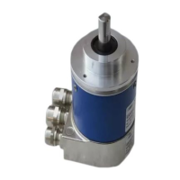
Explains bus covers and different encoder types.

4. Commissioning Procedures

4.1. Mechanical Mounting

Detailed instructions for mounting shaft and end shaft encoders.

4.2. Electrical Connection and Cabling

Procedures for connecting the bus cover and cabling.

Commissioning Details

Setting User Address and Bus Termination

Setting PROFIBUS node ID and bus termination resistors.

Connecting the Bus Cover

Step-by-step guide for connecting the bus cover cable gland.

M12 Connector and Bus Cover Assembly

M12 Connector and Bus Cover Assembly

Terminal assignments for M12 connectors and bus cover assembly.

5. Projecting the Encoder

5.1. Importing the GSD File

Steps to import the GSD file into the projecting software.

5.2. Encoder Bus Implementation

Dragging the encoder module into the hardware configuration.

5.3. Assigning Addresses for I/O Data

Assigning E/A addresses to input and output data.

Parameterization Overview

5.5. Parameterization Overview

Configuring encoder parameters via DP-Slave properties.

Parameter Assignment Details

Details on setting various encoder parameters.

Device-Specific Parameters

Device-Specific Parameters

Explanation of parameters like Code sequence, Class 4, Scaling, Resolution.

Multiturn Encoder Operation Notes

Multiturn Encoder Operation Notes

Notes on endless operation and parameter ratios.

5.5.3. Clock Synchronisation

5.5.3. Clock Synchronisation

Configuring clock-synchronous operation settings.

Configuration Settings and Loading

Clock-Synchronous Network Settings

Options for constant bus cycle time and slave synchronization.

5.6. Implementing Alarm Handling

Implementing OB82 and OB86 for alarm handling.

5.7. Configuration Compilation and Loading

Compiling and loading the project to the control.

6. Profibus Operation

6.1. Master Class 1 (Parameterization Master)

Encoder's role in parameterization master startup.

6.2. Status Indicator (Multi-colour LED)

Explains the meaning of the LED colors and states.

Telegram and Data Transmission

6.3. Telegram 81 of Profile PROFIdrive

Details input and output data structure for cyclic communication.

Data Readout and Preset Function

6.4. Position Readout

How position data is transmitted and accessed.

6.5. Error Signals in G1_XIST2

Interpretation of error codes in G1_XIST2.

6.6. Preset Function

How to set and save preset values.

6.7. Alarms

6.7. Alarms

How diagnosis alarms are triggered and their structure.

Warnings and Acyclic Data Communication

6.8. Warnings

Diagnostic warnings for internal tolerance limits.

6.9. Acyclic Data Communication (DPV1)

Overview of DPV1 acyclic services like DS_Read and DS_Write.

6.9.3. DS_Read Parameter Access

6.9.3. DS_Read

How to read parameters using system function SFB52/RDREC.

6.9.4. PROFIdrive Parameter 918 Node ID

6.9.4. PROFIdrive Parameter 918 Node ID

Readout of the PROFIBUS node ID.

6.9.5. PROFIdrive Parameter 922 Telegram Type

6.9.6. PROFIdrive Parameter 964 Device ID

6.9.6. PROFIdrive Parameter 964 Device ID

Readout of device identification data.

6.9.7. PROFIdrive Parameter 965 Profile Number

6.9.8. PROFIdrive Parameter 971 to Non-Volatile Memory

6.9.8. PROFIdrive Parameter 971 to Non-Volatile Memory

Storing parameters to non-volatile memory.

6.9.9. PROFIdrive Parameter 979 Sensor Format

6.9.9. PROFIdrive Parameter 979 Sensor Format

Readout of sensor format data block.

DS_READ for Parameter 979

DS_READ for Parameter 979

Reading sensor format data using DS_READ.

6.9.10. Profile Parameter 65000 Preset Value

6.9.10. Profile Parameter 65000 Preset Value

Reading or writing the preset value.

6.9.11. I&M Parameter 65000 Block 0

6.9.11. I&M Parameter 65000 Block 0

Readout of Identification & Maintenance block 0.

I&M Parameter Details

I&M Parameter Details

Detailed breakdown of I&M parameter values and meanings.

7. System Documentation: Profibus-DP

7.1. General Information

Overview of PROFIBUS, its variants, and characteristics.

7.2. GSD File

Role and information provided by the GSD file.

7.3. Encoder Operating Parameters

7.3. Encoder Operating Parameters

Description and values of operating parameters.

7.4. Data Exchange Between PROFIBUS-DP Devices

7.4. Data Exchange Between PROFIBUS-DP Devices

Steps of initializing, restart, and data communication.

Parameterization, Configuration, and Diagnostics

7.5. Parameterization and Configuration

Process of parameterizing and configuring the slave.

7.6. Diagnostic Signals

Utilization of alarms and warnings as diagnostic signals.

Diagnostic Data and Alarms

7.6.1. Diagnostic Data Block Description

Breakdown of diagnostic data bytes and their significance.

7.6.2. Alarms

Supported alarms like position error and lithium cell voltage.

8. Troubleshooting – FAQ

8.1. FAQ: Projecting

Answers to common projecting questions.

Projecting FAQs: Manual, GSD, and Classes

Info on manual, GSD file, and parameterization classes.

8.1.4. 32-bit Parameter Input in Siemens Step7

Splitting 32-bit parameters for Step7 input.

FAQ: Operation Topics

8.2. FAQ: Operation

Answers to common operation questions.

8.2.1. Position Readout

How position data is transmitted and accessed.

8.2.2. Setting and Saving Preset Value

Procedures for setting and saving preset values.

8.2.3. Bus Cover LED Function

Explanation of the bus cover LED status.

Operation FAQs and Troubleshooting

8.2.4. Altering Resolution

Process for changing the encoder resolution.

8.2.5. Reading Diagnostic Data

Methods for reading DPV2 diagnostic data.

8.3. FAQ: Troubleshooting

Answers to common troubleshooting questions.

8.3.1. No Encoder Communication (Yellow LED)

Troubleshooting steps for no communication.

Troubleshooting Communication Errors

8.3.2. No Encoder Communication (Red Flashing LED)

Troubleshooting steps for communication errors and parameterization issues.

Related product manuals