Do you have a question about the Baumer BMSV 58 and is the answer not in the manual?
This document describes the Baumer PROFINET absolute encoder, a precision sensing device designed for determining angular positions and revolutions, and supplying measured values as electrical output signals to a downstream device. The encoder system is modular, allowing for the combination of a basic encoder with various bus covers to suit different application requirements.
The PROFINET absolute encoder system consists of a basic encoder and a bus cover. The basic encoder is responsible for sensing angular positions and revolutions, offering different specifications regarding resolution, ambient conditions, and sensing methods. Available basic encoder types include singleturn and multiturn versions, with varying resolutions such as 12-bit (4096 steps per turn) for magnetic sensing (Magres/magtivo®), 13-bit (8192 steps per turn) for optical/magnetic sensing (Procoder/multivo®) in standard applications, and 18-bit (262144 steps per turn) for ultra-precise optical/magnetic sensing with integrated analog/digital conversion (Dignalizer/activo®/multivoPlus).
The bus cover integrates the fieldbus interface and all necessary electronic circuitry for processing the measured values. PROFINET communication is handled by a dedicated PROFINET-ASIC ERTEC200, which includes an integrated ARM9 high-performance micro-controller. This modular design allows for flexibility in combining basic encoders with bus covers that support various bus interfaces, including CANopen, DeviceNet, EtherCAT, Ethernet/IP, LIGHTBUS (fiber-optic), Profibus-DP, Profinet, Powerlink, Power over EtherCAT, and SAE J1939. All encoders, except those with a fiber-optic interface, support parameterization via the bus interface.
The encoder supports three PROFINET real-time classes: Realtime (RT) Class 1, Isochrone Realtime (IRT) Class 2, and Isochrone Realtime (IRT) Class 3. RT Class 1 offers a typical cycle time of 100ms or less and can use standard network components. IRT Class 2 operates without topology planning, with typical cycle times of 10ms or less, requiring all network components to support PROFINET IRT frame priority processing. IRT Class 3, designed for topology planning, achieves typical cycle times of 1ms or less, also requiring all network components to support PROFINET IRT frame priority processing. Position values are captured with high accuracy, typically +/- 1µs or better, relative to the bus clock.
The encoder provides input data (position value) and output data (preset value). Input data is transmitted cyclically as a consistent 32-bit, right-aligned data word in binary code, accessible by the PLC software using a double word. Output data allows the control system to set the encoder to a defined position value within its parameterized total sensing range. The preset function is triggered by setting bit 31 in the output data, with the preset value defined by bits 0-30. Bit 31 should remain set for at least 10ms to be recognized, and subsequent changes from '0' to '1' are evaluated.
Device-specific parameters include code sequence (clockwise or counter-clockwise rotation), steps per turn (singleturn resolution), and total measuring range. The encoder supports "Endless Operation" automatically if required, meaning there are no special requirements for the ratio between total measuring range and measuring units per revolution. This allows the encoder shaft to rotate unlimitedly even when unpowered, provided Endless Operation is active. If Endless Operation is inactive, the encoder must be referenced (presetted) after each power-up if unpowered motion cannot be avoided.
Commissioning involves mechanical mounting and electrical connection. For shaft encoders, mounting involves securing the encoder flange with screws and connecting the drive shaft using an appropriate coupling that compensates for temperature and mechanical tolerances. End shaft/hollow shaft encoders are mounted by fully opening a clamping ring, pushing the encoder onto the drive shaft, and tightening the ring. Various methods like adjusting elements with rubber buffers, mounting angles, or stud screws can be used.
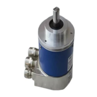
Electrical connection requires removing the bus cover by releasing fastening screws and lifting it axially. The bus cover features three M12 connectors: one A-coded for voltage supply (10-30 VDC) and two D-coded for PROFINET data communication. Unused cable glands should be sealed with a sealing bolt. PROFINET uses Fast Ethernet cable (100MBit, Cat 5) with four AWG22 wires, available in Type A (rigid), Type B (flexible), and Type C (highly flexible) variants.
Projecting the encoder involves importing a GSDML file into the projecting software (e.g., Siemens® Step7®). After import, the encoder can be dragged from the hardware catalog to the bus rail, and its module "Encoder data 32Bit EA" can be plugged into the module window. Device identification requires assigning a unique device name in the PROFINET network, which is transmitted online to the device and saved in non-volatile memory. I/O addresses for input and output data must be assigned to enable access by the control software.
For IRT Class 3 operation, topology planning is necessary, where port connections and cable lengths between system components are defined in the project. This allows the projecting tool to optimize overall performance by considering cable, port, and switch delay times. Parameterization of the encoder, such as rotational direction, steps per revolution, and total measuring range, is performed via the projecting tool.
During PROFINET operation, an automated boot-up procedure assigns an IP address and establishes communication. The encoder's operating status is indicated by a multi-color LED on the bus cover: yellow continuous for no PROFINET link, green continuous for an active PROFINET link and cyclic data transmission, red continuous for position leaps or overspeed, red flashing slowly (1 Hz) for parameterization errors, and red flashing fast (5 Hz) for inadmissible preset values. Two additional green LEDs signal bus activity on ports P1 and P2.
The manual emphasizes safety instructions for transport, storage, mounting, and electrical commissioning. Encoders should only be transported and stored in their original packaging and protected from shocks. During mounting, impacts on the housing or shaft should be avoided, and rigid connections between encoder and drive shafts are prohibited for shaft encoders. The encoder should not be opened or mechanically modified, as this can damage internal components and compromise reliable operation.
For electrical commissioning, no modifications should be made to the encoder, and wiring should not be performed while the encoder is live. Connectors should not be plugged or unplugged when live, though the bus cover can be removed or docked to the basic encoder while live. The entire system must comply with EMC/EMI requirements, with encoder and supply cables installed separately from high-interference sources. Separate supply voltage should be provided for encoders when working with high-interference consumers. The encoder housing and connecting cables must be completely shielded, with the braided shield connected to the cable gland or connector, ideally with dual connection to protective earth (PE).
The encoder's internal offset, calculated during a preset operation, is stored non-volatile in Flash memory to maintain position after power-off and power-on. While Flash memory provides 100,000 writing cycles, frequent preset operations should be considered in the control software configuration to manage this capacity. Any alteration of the total measuring range during re-parameterization will clear the internal preset-offset value, which is generally not an issue as the position is lost anyway in such cases.
Troubleshooting guidance is provided for common issues. If there is no encoder communication (LED yellow continuous), potential causes include a broken PROFINET connection, an incorrect device name, incorrect encoder implementation in the PROFINET project, or a compiled project not exported to the control. If the LED flashes red once per second, it indicates incorrect encoder parameterization, often due to the total measuring range not being aligned with the altered encoder resolution. The manual provides examples for calculating admissible measuring ranges for singleturn and multiturn encoders to prevent such errors.
| Fiber Type | Multimode |
|---|---|
| Transmission Distance | Up to 2 km |
| Storage Temperature | -40°C to +85°C |
| Weight | 150 g |
| Humidity | 5% to 95% (non-condensing) |