Manual_PROFINET_EN.doc 8/24 www.baumer.com
17.10.11
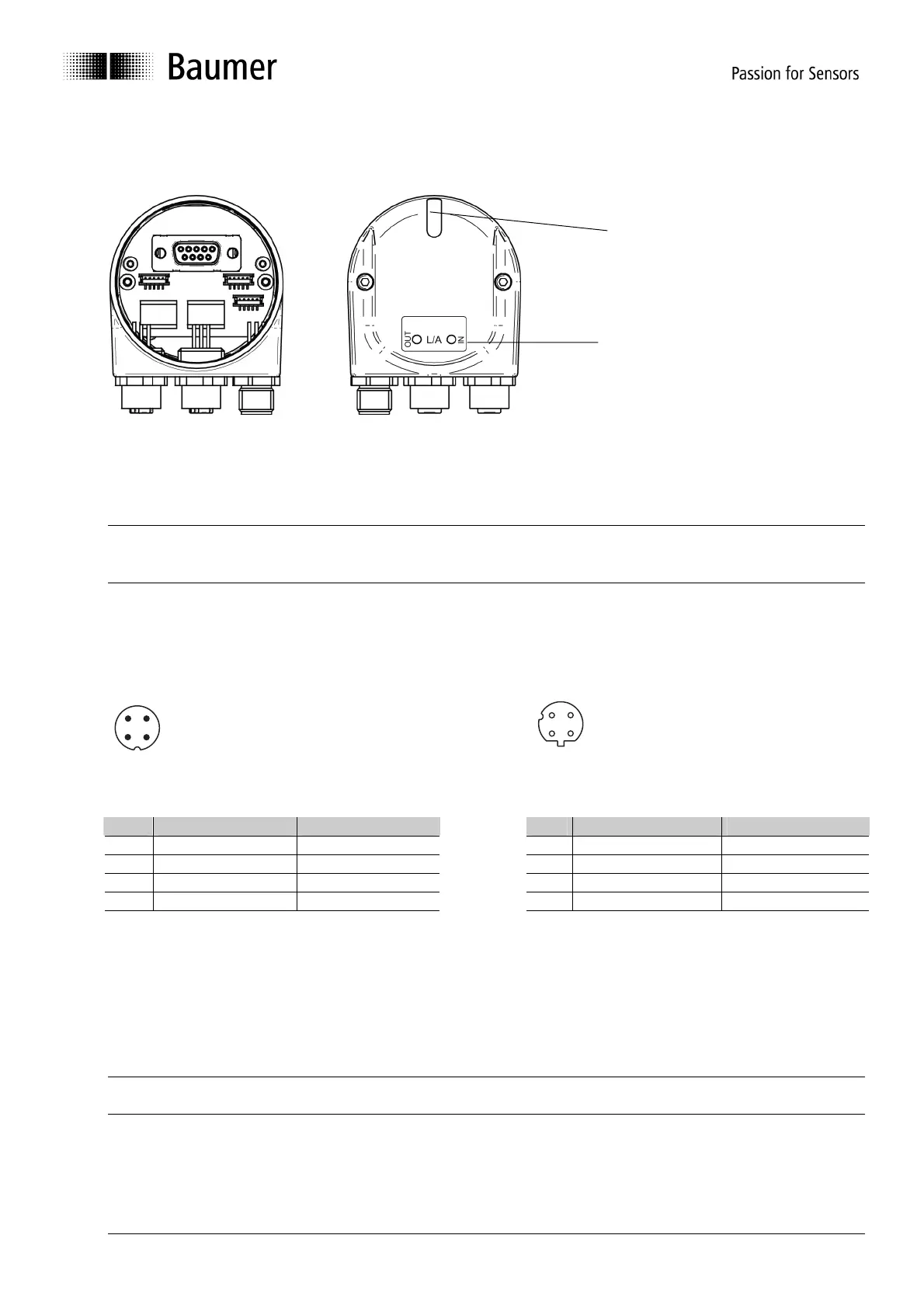
4.2.2. Connecting the bus cover
The bus cover provides three M12 connectors.
Two M12 connectors (D-coded, according IEC 61076-2-101) serve for PROFINET connection.
• For voltage supply use A-coded M12 connector only.
• For the bus lines both D-coded M12 connectors may be used at will.
• Seal up the unused cable gland using a sealing bolt (included in the delivery).
There is no need to proceed any manual settings inside the bus cover. PROFINET does not require setting a
node ID and terminating resistor like Profibus. All address parameters are configured by the projecting tool
(e.g. Siemens
®
Step7
®
).
Pin assignment
Supply voltage
1
3
4
2
PROFINET (data communication line)
4
3
1
2
1 x M12- connector (male) 2 x M12-connector (female)
A-coded D-coded
Pin Assignment Wire color
Pin Assignment Wire color
1 UB (10...30 VDC) brown 1 TxD+ yellow
2 N.C. white 2 RxD+ white
3 GND blue 3 TxD- orange
4 N.C. black 4 RxD- blue
Assembly of basic encoder and bus cover:
• Carefully plug the bus cover onto the D-SUB connector of the basic encoder, then press it over the seal
taking care not to tilt it.
• Tighten both fastening screws firmly in the same direction.
• The bus cover must fully rest on the housing of the basic encoder and be firmly screwed on.
The encoder housing and braided shield of the connecting cable are only ideally connected if the bus cover is
resting fully on the basic encoder (positive locking).
Multi-color LED
Indicating the operating status,
green-yellow-red
Activity – LEDs (green)
to signal bus activity on
Port1, Port2