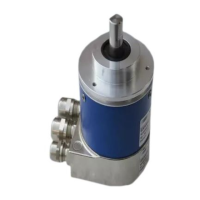
This document describes the Baumer absolute encoder with a POWERLINK interface (Bus cover), designed for precision sensing in industrial applications.
Function Description
The Baumer absolute encoder is a modular device comprising a basic encoder and a bus cover. This modular architecture allows for flexibility, as different basic encoders (varying in accuracy, ambient conditions, and sensing principles) can be combined with bus covers integrating various bus systems. The POWERLINK bus cover, specifically, handles all measured value processing and Ethernet communication, acting as the communication link between the POWERLINK network and the basic encoder. It supports encoder profile 406 and POWERLINK specification V2.0.
The encoder determines angular positions and revolutions, providing measured values as electrical output signals to downstream devices. It is designed for static PDO mapping, meaning Process Data Objects (PDOs) are identical to the position in Object 6004h. For firmware version 1.5.0 and higher, the speed value (in counts per second) is also transmitted within the PDO (Object 6030h). The PDO's position data consistently reflects the value acquired by the SoC (Start of Cycle) in the last cycle.
A key feature of the POWERLINK bus cover is its integrated Hub, which enables the formation of a Daisy Chain network topology. The Ethernet interface also supports Auto-Negotiation functionality, simplifying connectivity by allowing the use of straight or crossed Ethernet cables and direct connections to the control system without additional Ethernet hubs.
The device offers extensive parameterization capabilities via the bus interface, allowing users to configure communication behavior and encoder-specific features. This includes setting the Node ID, which can be done either through software or hardware switches. If hardware switches are set to '0', the software configuration takes precedence.
Important Technical Specifications
POWERLINK Specifications:
- POWERLINK Version: 2.0
- CANopen Profile: CiA 406 (encoders)
- Minimum Cycle Time: 250 µs
Ethernet Specifications:
- MTU: 300 Bytes
- Delay Internal Hub (Daisy Chain): 400 ns/Node
- Max. Response Time: 2 µs (incl. hub delay)
- Transmission Rate: 100 Mbit/s semi-duplex
- Ethernet Outputs: 2 outputs; M12 D-coded (Auto-Negotiation)
Timing Behavior (Delay typical / Jitter):
- BMS (ST): 11.24 µs / +- 7.6 µs (= 7.5 µs / +- 68 ns)
- BMMx (MT): 10.84 µs / +- 10.1 µs (= 10 µs / +- 68 ns)
- GXAMx (ST): 5.00 µs / +- 0.54 µs (= 0.54 µs / +- 68 ns)
- GBAMx (ST): 5.00 µs / +- 0.6 µs (= 0.54 µs / +- 68 ns)
- GXMMx (MT): 7.20 µs / +- 1.3 µs (= 1.2 µs / +- 68 ns)
- GBMMx (MT): 7.20 µs / +- 1.3 µs (= 1.2 µs / +- 68 ns)
Physical Resolution (examples):
- BMS ST: 4000h (14 Bit) ST Resolution, 4000h (14 Bit) Total Resolution
- BMMx MT: 4000h (14 Bit) ST Resolution, 1 0000h (18 Bit) MT Resolution, 1 0000 0000h (32 Bit) Total Resolution
- GXAM ST: 2000h (13 Bit) ST Resolution, 2000h (13 Bit) Total Resolution
- GXMMx MT: 2000h (13 Bit) ST Resolution, 1 0000h (16 Bit) MT Resolution, 2000 0000h (29 Bit) Total Resolution
- GBAM ST: 4000h (18 Bit) ST Resolution, 4000h (18 Bit) Total Resolution
- GBMM MT: 4000h (18 Bit) ST Resolution, 4000h (14 Bit) MT Resolution, 1 0000 0000h (32 Bit) Total Resolution
Service Data Objects:
- NMT_DeviceType_U32 (1000h): Device type (e.g., Multiturn encoder: 0002'0196h, Singleturn encoder: 0001'0196h).
- NMT_StoreParam_REC (1010h): Stores parameters (save all, communication, application).
- NMT_RestoreDefParam_REC (1011h): Loads factory configuration (load all, communication, application, manufacturer parameters).
- NMT_IdentityObject_REC (1018h): General product information (Vendor ID, Product Code, Revision Number, Serial Number).
- PDO_TxCommParam_0h_REC (1800h): PDO Communication parameters (Node ID, Mapping Version).
- PDO_TxMappParam_0h_AU64 (1A00h): PDO Mapping parameter (ObjectMapping 1 for position, ObjectMapping 2 for position and speed).
- NMT_FeatureFlags_U32 (1F82h): Supported features (Isochronous, SDO by UDP/IP, SDO by ASnd, Multiplexed Access).
- NMT_EPLVersion_U8 (1F83h): POWERLINK Communication profile version.
- NMT_EPLNodeID_REC (1F93h): Definition of Node ID (active Node ID, NodeID setup by HW/SW switch).
Application Parameters:
- Operating Parameters (6000h): Bit 0 for Rotation CCW, Bit 2 for Scaling function active.
- Measuring Units per Revolution (6001h): Singleturn resolution in steps/revolution.
- Total Measuring Range in Measuring Units (6002h): Total measuring range in steps.
- Preset Value (6003h): Sets actual position to preset value.
- Position Value (6004h): Actual position.
- Operating Status (6500h): According to object 6000h.
- Single-Turn Resolution / Measuring Step (6501h): Currently used Singleturn resolution.
- Number of distinguishable Revolutions (6502h): Physically distinguishable revolutions.
- Alarms (6503h): Evaluated alarms (Bit0: Position alarm).
- Supported Alarms (6504h): Supported alarms (Bit0: Position alarm).
- Warnings (6505h): Evaluated warnings (Bit4: Battery charge).
- Supported Warnings (6506h): Supported warnings (Bit4: Battery charge).
- Profile and Software Version (6507h): Software and profile version.
- Operating Time (6508h): Not supported.
- Offset Value (6509h): Offset value in steps (non-scaled).
- Serial Number (650Bh): Serial number.
- Speed Sample Rate (2020h): Update rate of speed calculation.
- Speed Averaging time (2021h): Averaging time of speed calculation.
- Speed Value (6030h): Speed value in counts per second (cps).
Electrical Connection:
- Voltage Supply (M12 male, A-coded): Pin 1: UB (10-30 VDC, brown), Pin 3: GND (blue).
- POWERLINK (data line) (2x M12 female, D-coded): Pin 1: TxD+ (yellow), Pin 2: RxD+ (white), Pin 3: TxD- (orange), Pin 4: RxD- (blue).
Usage Features
The encoder is designed for straightforward integration into industrial automation systems, particularly with B&R Automation Studio. The process involves:
- Importing the xdd file: This is done via the "Tools -> Import Fieldbus Device" menu in Automation Studio. The xdd file contains the device description for the POWERLINK encoder.
- Adding the encoder module: Once the xdd file is imported, the Baumer encoder can be added as a module using "Insert -> Module" in the software.
- Defining Node ID: The Node ID can be configured either through software settings or by using hardware switches on the device. If hardware switches are set to '0', the software configuration is applied.
- Configuring I/O: The I/O encoder configuration can be accessed via the context menu of the module, allowing for detailed setup of cyclic transmission objects like position and operating parameters.
- Monitoring: In running mode, the hardware project allows for real-time monitoring of the current status and position readout in the encoder's I/O mapping.
The scaling function allows users to adjust the singleturn resolution and total measuring range. For example, a GXMMW encoder with a physical resolution of 13/16 Bit ST/MT (8192 steps/rev., 65536 revolutions) can be configured for a desired singleturn resolution of 3600 steps/revolution and a total measuring range of 235929600 steps (3600 steps/revolution x 65536 revolutions). It's important to note that if the actual position exceeds the number of physically distinguishable revolutions, the position value will change after power off/on.
Maintenance Features
The manual emphasizes several safety precautions and operating instructions crucial for the device's longevity and reliable operation:
- Transport and Storage: Always transport and store the encoder in its original packaging. Avoid dropping the encoder or exposing it to major shocks.
- Mechanical Mounting:
- For solid shaft encoders, mount using the provided mounting holes and screws, ensuring the drive shaft and encoder shaft are connected with an appropriate coupling that compensates for temperature and mechanical backlash. Tighten mounting screws firmly.
- For blind hollow shaft encoders, mount by clamping ring, adjusting element with rubber buffer, or spring washer, ensuring a firm attachment to the drive shaft and contact surface.
- Avoid impacts, shocks, twist, or torsion on the housing and shaft. Do not open the encoder or perform mechanical modifications, as this can damage internal components and compromise operation.
- Electrical Connection:
- Always handle the bus cover in an ESD bag.
- To connect the bus cover, release fastening screws, carefully lift off the cover, plug it onto the D-SUB connector of the basic encoder, slide it over the seal without cocking, and then firmly and equally tighten the fixing screws. An optimum connection is ensured when the bus cover mounting surface fully rests on the basic encoder.
- Do not perform electrical modifications or wiring work while the encoder is live.
- Ensure the entire system complies with EMC/EMI requirements. Install encoder and supply cables separately from high-interference sources. Provide separate encoder supply voltage for high-interference consumers.
- Completely shield the encoder housing and connecting cables, connecting the braided shield to the cable gland or connector. Ideally, aim for dual connection to protective earth (PE) via mechanical assembly and cable shield. If earth loop problems occur, earth at least on one side.
Display Elements for Status Monitoring:
- Link/Activity LEDs: Indicate Ethernet interface activity (off: no link, on: link available, flickering: Ethernet activity).
- Status DUO LED (red/green): Indicates bus cover activity.
- Green LED: Off (bus cover off or booting), flickering (pre-operational), on (operational), single flash (in reset), double flash (reset status), triple flash (aborted or inactive), quadruple flash (Basic Ethernet).
- Red LED: Off (no error), on (error).
These features ensure that the device can be installed, configured, and maintained effectively, with clear indicators for operational status and potential issues.