6
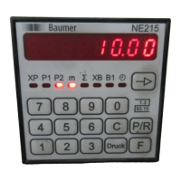
NE215
Counter connect
GND
RxD
TxD
RS232
26 25 24 23
22 21
RS485
T, R +
T, R -
1 Relay contact output P1
1 Relay contact output B1
1 Relay contact output P2
3 Counter connect
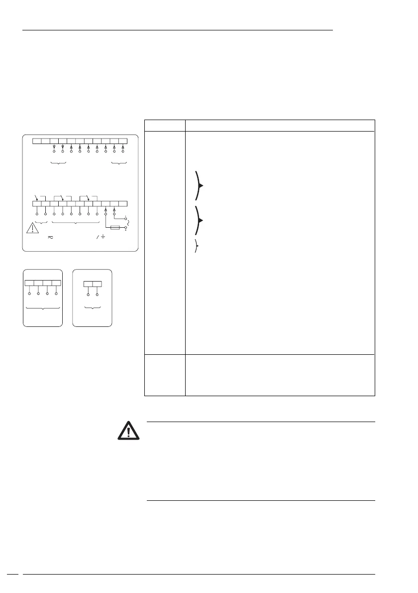
This chapter will explain how the contacts are assigned.
Under chapters 3.1 to 3.5 you will find actual tips and technical data
for the various connections.
The electrical inputs and outputs are assigned to two 12-pole plug-in
screw terminals, coded to prevent reversed polarity.
Assignment
Contact Function
1 Not assigned
2 Supply voltage
3 Supply voltage
4
5
6
7
8
9
10
11
12 Signal input, track A
13 Signal input, track B
14 Reset XP
15 Time meter
16 Signal input, track B1
17 Reset B1
18 Coding input for input logic
19 Encoder supply 0 Volt
20 Encoder supply +24 Volt
21 Option RS485 T,R-
22 Option RS485 T,R+
23 Option RS232 TXD
24 -
25 Option RS232 RXD
26 Option RS232 GND
Litz contact only by means of connector sleeves with insulating
enclosures for reasons of shock protection according to VDE 0411
part 100. Do not otherwise assign contacts that have been left
unassigned ex factory. We recommend to screen all encoder
terminal leads and to ground the shield on one side. Shields on
both sides are recommended in case of RF interference or in case
of equipotential bonding over long distances. The encoder leads
should not be in the same phase winding as the MAINS supply and
the output contact leads.
max. 250 V Terminal - Terminal - Terminal
Output
B1 P2 P1
BA
Count
+24V 0V
Sensor
supply
NPN Br. 18-20
PNP Br. 18-19
B1 reset
B1 counter
(Scaling on)*
XP reset
Supply
22 21 20 19 18 17 16 15 14 13 12
11 10 9 8 7 6 5 4 3 2 1
h counter
* Models with scaling