Do you have a question about the Baumer NE215 and is the answer not in the manual?
| Brand | Baumer |
|---|---|
| Model | NE215 |
| Category | Cash Counter |
| Language | English |
Explains symbols used in the operating manual for clarity.
Details general safety precautions, proper use, and responsibilities for safe operation.
Covers safety aspects during installation and commissioning procedures.
Outlines safety measures for maintenance and repair work.
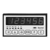
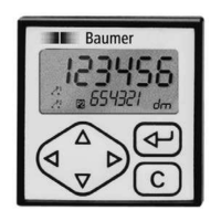
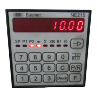
Identifies and describes the main components and LED display of the counter.
Details the function of each key on the counter's control panel.
Presents a diagram illustrating the counter's internal components and connections.
Lists terminal assignments and their corresponding functions for counter connections.
Explains how to connect the power supply to the counter.
Describes the assignment of signal outputs using relay contacts.
Details the assignment of signal inputs for counting functions.
Provides instructions for connecting the encoder supply.
Explains how to connect the serial interface (RS232).
Guides the user through executing the counter's test routine.
How to read and reset the main counter status.
Steps to read and change the main counter preset value.
How to read and reset the totalizing counter.
How to read and reset the secondary counter status.
How to read and change the secondary counter preset value.
How to read the time meter.
Introduces the four segments of the programming mode.
Explains the function of various keys in programming and operating modes.
Step-by-step guide to enter the programming mode.
Procedures for incorrect or unknown security codes.
Details parameters for the first programming segment.
Explains status selection for operating parameters in segment 2.
Covers machine-related functions and values in segment 3.
Details interface parameters in the fourth programming segment.
Describes different operating modes like Step preset and Self-adjusting preset.
Explains counting modes for main and totalizing counters.
Details various output signal responses and their configurations.
Lists display, power, inputs, frequency, and storage specifications.
Covers dimensions, mounting, housing, weight, and environmental conditions.
Details general ratings, protection classes, and interference immunity.
Provides detailed dimensions and required cutout for mounting.
Lists parameters programmed at the factory before delivery.
Explains common error messages and how to clear them.
Introduces the RS485 open interface for remote control and data access.
Describes the ASCII-based transmission protocol and character structure.
Explains how to read data from storage locations using commands.
Illustrates reading various parameters via the interface.
Details how to program data into storage locations.
Demonstrates programming preset values and output times.
Command to clear specific counter values.
Command to switch the counter between programming and run modes.
How to read device type, programming number, date, and version.
Command to clear specific error messages on the counter display.
Command to initiate printouts of specific counter lines.
Describes the format of printouts and how XP values are printed.
Details printout formats for preselections and the totalizer.
How to print data using the device's [Print] key.
Explains errors occurring during PC data transfer and responses.
Details the structure and types of error messages returned.
A table listing control characters used in communication protocols.
Provides a summary of operating plan lines and their descriptions.
Programming for status and principal count system operating modes.
Configuration of batch counter scaling factor and frequency.
Programming for reset functions and output times.
Programming for preselection takeover and function key address.
Configuration for batch counter function and tachometer settings.
Programming options for time meter function and code setting.
Configuration of baud rate, parity, address, and stop bits.
Describes the features and parameters of the RS232 closed interface.
Describes the features and parameters of the RS485 open interface.
Lists modifications to previous chapters regarding interfaces.
Details DIP switch settings for printers used with the counter.
New pin assignment for activating the scaling factor.
Details pin 15 activation for scaling factor setting.
Explains how to program the scaling factor for the main counter.
Lists technical specifications for the PTB-version encoder.
Details the order designation codes for selecting encoder options.
Maps encoder pin assignments to cable colors.
Describes encoder output signals and their sense.
Provides dimensional drawings for encoder mounting flanges.