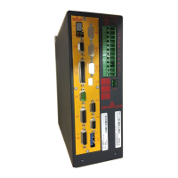
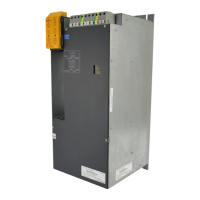
Installation
Instruction handbook BUM 60 / BUS 60
Document No.: 5.01032.05
49
of 82
7
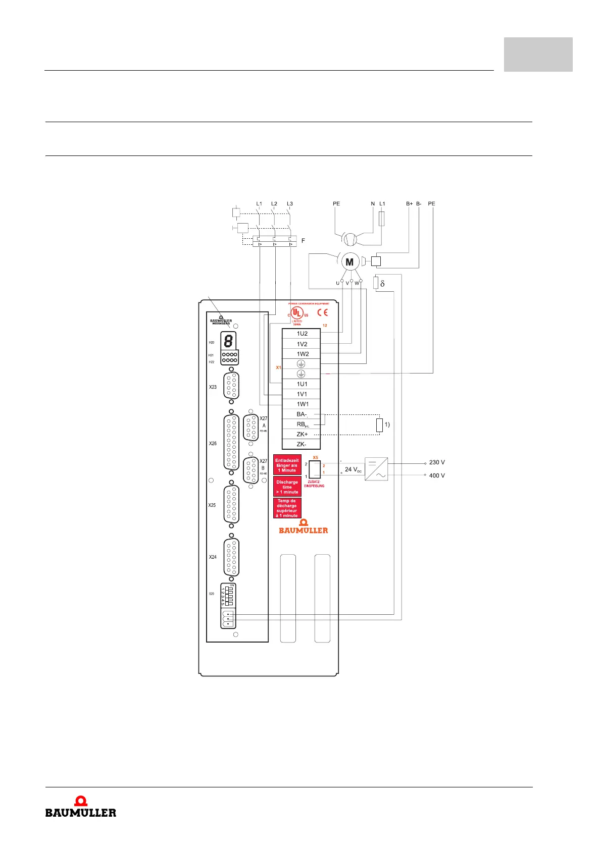
7.9 Connection diagrams
7.9.1 Connection diagram BUM 60
Display
Main contactor K1
Fuse or
circuit breaker
Power supply 3x400 V
Fan
Brake
or
1)
When using an external ballast resistor, remove wire bridge between RBint and BA- and connect the external ballast
resistor to X1:2 and X1:4
If UL508C has to be observed: the external ballast resistor must protect itself from overheating
Figure 7: Connection diagram BUM 60