22
DC Power Source Installation
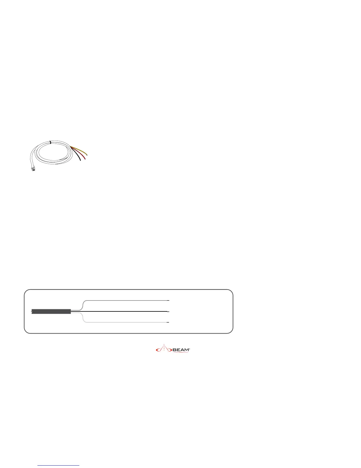
The DC power cable has three wires, RED, BLACK
and YELLOW. The RED and BLACK wires are used
for the power connection while the YELLOW
wire can be connected to a vessels accessories,
ignition or other similar circuits to control
the ON/OFF status of the IsatDock2 PRO in
synchronization with a vessels operation.
By default, the IsatDock2 PRO will stay on for 20
minutes after this input (YELLOW wire) is switched
o. If a call is in progress while this occurs, the
IsatDock2 PRO will stay on for 20 minutes after the
call is terminated. Please follow the steps below to
connect the DC power cable to the vehicle battery
power and the IsatDock2 PRO.
1. Route the wire end of the DC power cable
to the connection point.
2. Connect the BLACK wire to the negative
terminal of the battery (10A fuse
recommended) or the vehicle chassis (if
negatively grounded chassis).
3. Connect the RED wire to the positive
terminal of the battery. It is recommended
to add the 5A fuse (supplied) between
them.
4. Connect the YELLOW wire to the vehicle
accessory power. If the accessory power
is unavailable, this may be connected
to a vehicle ignition voltage. It is
recommended to add a 1A fuse between
them. The accessory wire enables the
IsatDock2 PRO to turn on and o as the
vehicle key is enabled or disabled. If this
function is not required, the YELLOW wire
MUST be connected to the RED wire.
YELLOW
BLACK
RED