23
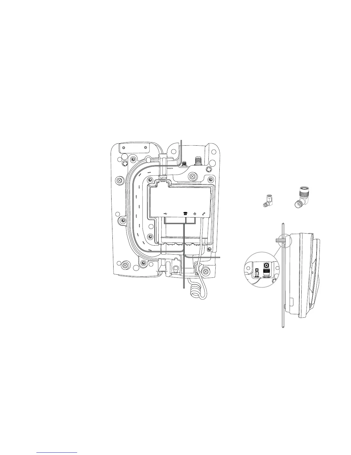
8) Cable Routing
The IsatDock2 PROvides three
dierent cable routing options when
installing the docking station.
Cables may exit via path ‘A’ that travels
around to the top of the dock allowing
for the interface cables to be run with
the external antenna connections.
Path ‘B’ directs cables out the base of
the dock while path ‘C’ results in cables
exiting to the side.
A = TOP cable route
B = BOTTOM cable route
C = LHS cable route
Optional through-wall
Right angled adapters are optionally tted to the
external antenna connectors to allow routing of
cables through a wall. A “clean” installation free of
any visible cabling can be achieved with the use
of right angled connectors and by running the
interface cables along path A.
A
B
C
SMA Adapter (GPS)
TNC Adapter (GSPS)