To eliminate Service Search
on UHF, HI VHF, or LO VHF ranges
PRESS:
'
I
UHF~
,w
or
To restore Service Search
on ranges previously eliminated
PRESS:
,
or again.
To stop during service search,
PRESS:
I
Hold
I
To manually advance Service Search,
PRESS:
1
Hold
I
To resume Service Search,
PRESS:
I
~esumel
To enter a Service Search frequency
into a channel, PRESS
IE]
.
NOTE: Service search mode of operation is cancelled when any of the
following keys are pressed
.
,
thru
-
NOTE: Although most active frequencies are in the
11
Service
Search categories, there will be some active frequencies in
many areas which are not included. These may be programm-
ed into the 50 user-programmable channels.
AUXILIARY FUNCTION
When the auxiliary function is activated selectively on a channel,
(PRESS:
Fl
)
a dot will appear at the lower-right corner. Each
time the scanner detects a signal on this channel, the AUX. terminal
on the rear apron of your Bearcat
300
will provide a closed circuit of
up to
500
milliamperes of current. This will turn on many remote con-
trolled battery-operated cassette recorders without additional ac-
cessories. NOTE: Some recorders may require additional interface
equipment for control or audio. This should be installed by a qualified
technician.
Audio for the recorder input is provided by: The External- Speaker
jack which will disconnect the internal speaker for silent recording; or
the Tape jack which allows the speaker to remain on for audible
monitoring while recording.
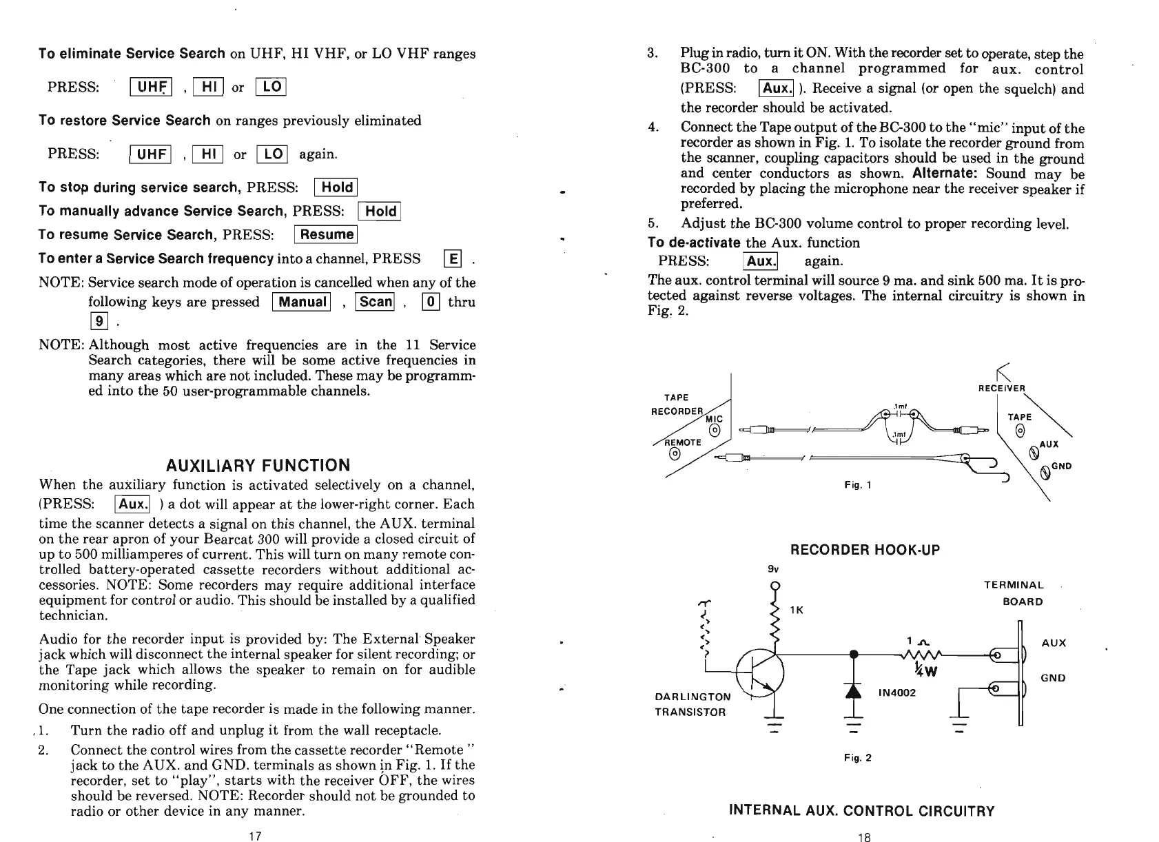
One connection of the tape recorder is made in the following manner.
,l.
Turn the radio off and unplug it from the wall receptacle.
2.
Connect the control wires from the cassette recorder "Remote
"
jack to the AUX. and GND. terminals as shown in Fig.
1.
If the
recorder, set to "play", starts with the receiver OFF, the wires
should be reversed. NOTE: Recorder should not be grounded to
radio or other device in any manner.
3.
Plug
in
radio, turn it
ON.
With the recorder set
to
operate, step the
BC-300 to a channel programmed for aux. control
(PRESS:
ml).
Receive a signal (or open the squelch) and
the recorder should be activated.
4.
Connect the Tape output of the BC-300 to the "mic" input of the
recorder as shown in Fig.
1.
To isolate the recorder ground from
the scanner, coupling capacitors should be used in the ground
and center conductors as shown.
Alternate:
Sound may be
recorded by placing the microphone near the receiver speaker if
preferred.
5.
Adjust the BC-300 volume control to proper recording level.
To de-activate
the Aux. function
PRESS: again.
The aux. control terminal will source
9
ma. and sink 500 ma. It is Dro-
tected against reverse voltages. The internal circuitry is show; in
Fig.
2.
RECEIVER
Fig.
1
RECORDER HOOK-UP
9v
TERMINAL
~
BOARD
L-
1
A
AUX
%
GND
DARLINGTON
I N4002
TRANSISTOR
Fig.
2
INTERNAL AUX. CONTROL CIRCUITRY