EXTERNAL ANTENNA
In some areas, unauthorized mobile police receivers are unlawful; be
sure to check with local authorities before installing your unit.
The telescoping antenna provided with your
Bearcat
300
is recom-
mended for most monitoring. For weak-signal reception, or for
electrically-noisy locations, an appropriate external antenna designed
for multi-band coverage should be connected to the unit via coaxial
cable.
RG-58U
is recommended for lengths of up to
50
feet. For
longer lengths
RG-8U
is recommended.
Your Bearcat
300
is equipped with an automotive type of external
antenna jack, and a mating plug (supplied) must be used.
An outside antenna needs only to be high enough to clear sur-
rounding obstructions. Above all, STAY AWAY
FROM
POWER
LINES!
You may be killed upon contact of the antenna with a power
line.
EXTERNAL SPEAKER
Although the internal speaker of the scanner will provide ample room
volume, in some applications an external speaker such as the Bearcat
B-45 may be desired. The external speaker should be plugged into the
rear-apron jack which will cut off the internal scanner speaker.
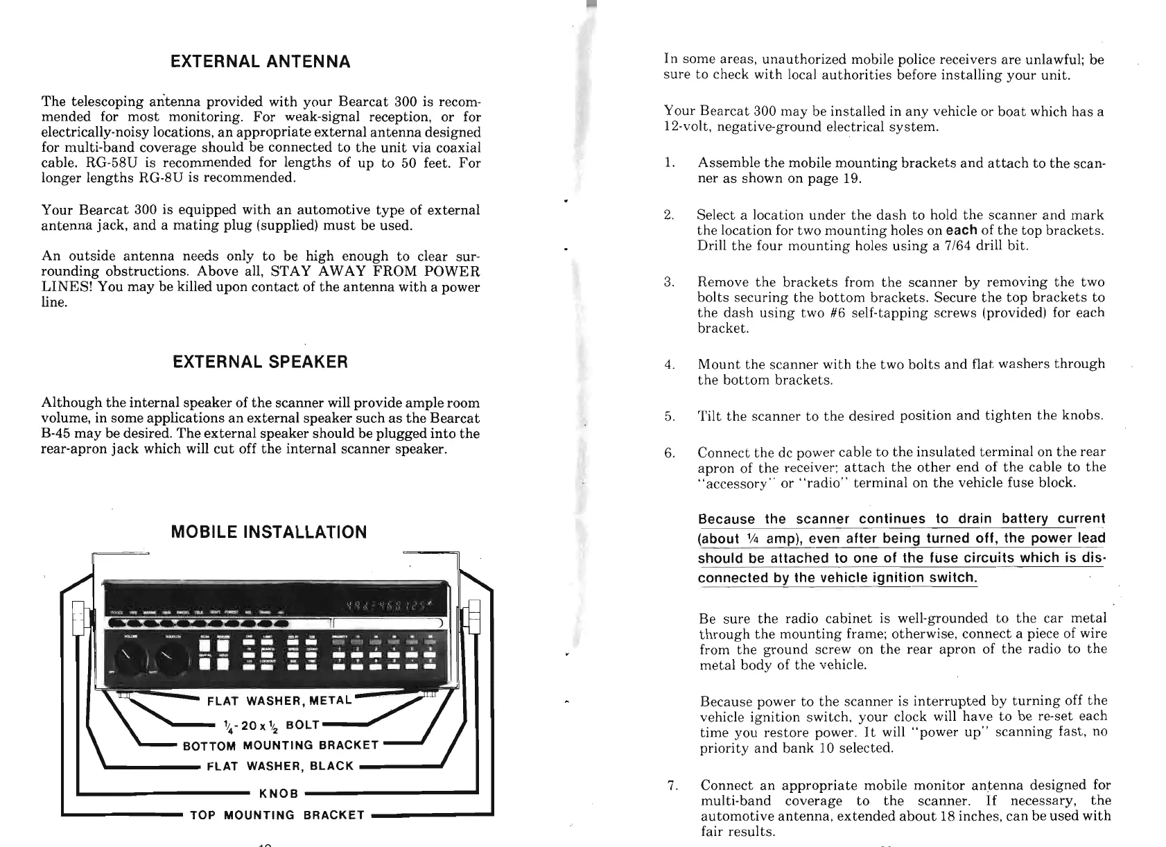
MOBILE INSTALLATION
I I
-
FLAT WASHER, BLACK
I
I
KNOB
-
TOP MOUNTING BRACKET
Your Bearcat
300
may be installed in any vehicle or boat which has a
12-volt, negative-ground electrical system.
1.
Assemble the mobile mounting brackets and attach to the scan-
ner as shown on page
19.
2.
Select a location under the dash to hold the scanner and mark
the location for two mounting holes on
each
of the top brackets.
Drill the four mounting holes using
a
7/64
drill bit.
3.
Remove the brackets from the scanner by removing the two
bolts securing the bottom brackets. Secure the top brackets to
the dash using two
#6
self-tapping screws (provided) for each
bracket.
4.
Mount the scanner with the two bolts and flat washers through
the bottom brackets.
5.
Tilt the scanner to the desired position and tighten the knobs.
6.
Connect the dc power cable to the insulated terminal on the rear
apron of the receiver: attach the other end of the cable to the
"accessory" or "radio" terminal on the vehicle fuse block.
Because the scanner continues to drain batterv current
(about
lh
amp), even after being turned off, the power lead
should be attached to one of the fuse circuits which is dis-
connected by the vehicle ignition switch.
Be sure the radio cabinet is well-grounded to the car metal
through the mounting frame; otherwise, connect a piece of wire
from the ground screw on the rear apron of the radio to the
metal body of the vehicle.
Because power to the scanner is interrupted by turning off the
vehicle ignition switch, your clock will have to be re-set each
time you restore power. It will "power up" scanning fast, no
priority and bank 10 selected.
7.
Connect an appropriate mobile monitor antenna designed for
multi-band coverage to the scanner. If necessary, the
automotive antenna, extended about 18 inches, can be used with
fair results.