SAFETY INSTRUCTIONS (Cont'd.)
OPERATING INSTRUCTIONS
Outdoor Antenna Grounding
-
Many of the Bearcat radios have provisions
for connection to an outside antenna. An outside antenna should be located
away from power lines. The antenna system must be grounded to provide
protection against voltage surges and built up of static charges. The antenna
system should be installed only by qualified service personnel. Section 810 of
the National Electric Code,
ANSIINFPA No. 70-1978 provides information
with respect to proper grounding of the mast and supporting structure,
grounding of lead-in wire to an antenna discharge unit, size of grounding con-
ductors, location of antenna-discharge unit, connection to grounding elec-
trodes, and requirements for the grounding electrode.
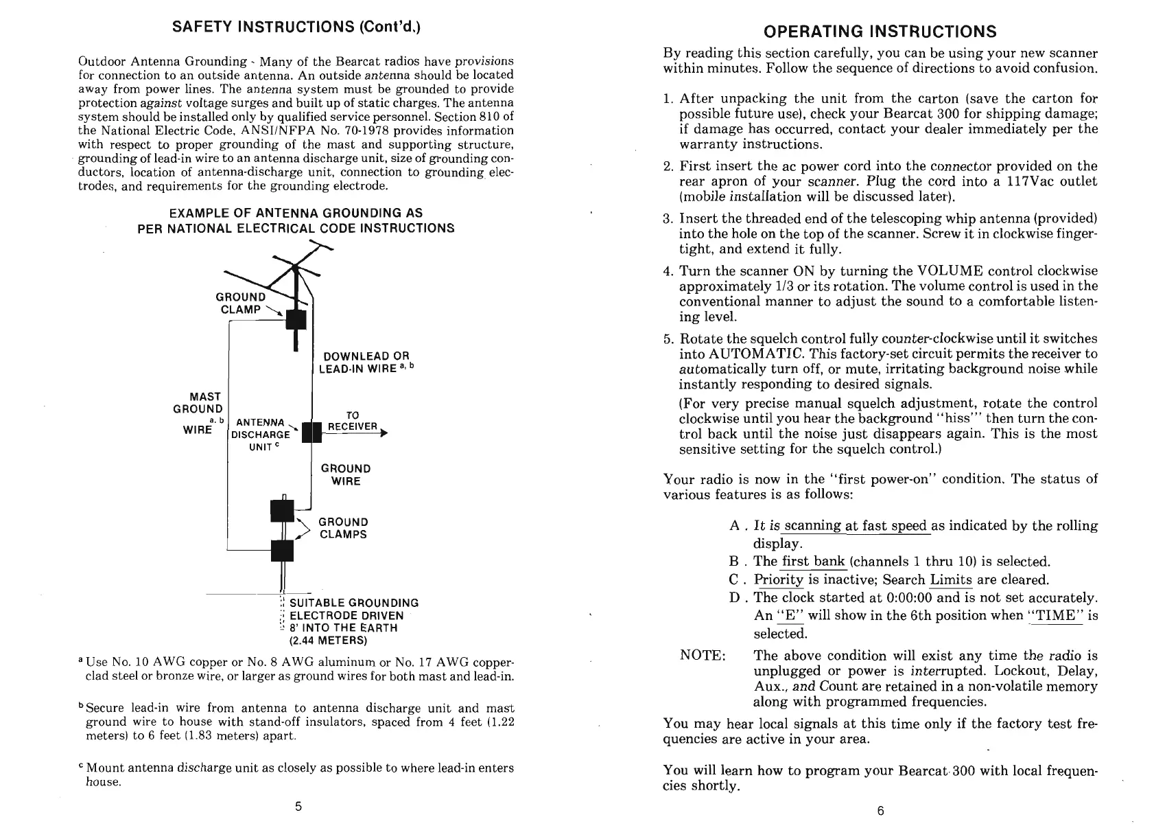
EXAMPLE OF ANTENNA GROUNDING AS
PER NATIONAL ELECTRICAL CODE INSTRUCTIONS
h
I
'I
DOWNLEAD OR
LEAD-IN WlRE
MAST
I
1
ROUND
1
I
,,
I
GROUND
1
WIRE
GROUND
CLAMPS
ii
SUITABLE GROUNDING
:;
ELECTRODE DRIVEN
:I
.'
8'
INTO THE EARTH
(2.44
METERS)
a
Use No. 10 AWG copper or No.
8
AWG aluminum or No. 17 AWG copper-
clad steel or bronze wire, or larger as ground wires for both mast and lead-in.
bSecure lead-in wire from antenna to antenna discharge unit and mast
ground wire to house with stand-off insulators, spaced from
4
feet (1.22
meters) to
6
feet (1.83 meters) apart.
Mount antenna discharge unit as closely as possible to where lead-in enters
house.
By reading this section carefully, you can be using your new scanner
within minutes. Follow the sequence of directions to avoid confusion.
1.
After unpacking the unit from the carton (save the carton for
possible future use), check your Bearcat 300 for shipping damage;
if damage has occurred, contact your dealer immediately per the
warranty instructions.
2.
First insert the ac power cord into the connector provided on the
rear apron of your scanner. Plug the cord into a 117Vac outlet
(mobile installation will be discussed later).
3.
Insert the threaded end of the telescoping whip antenna (provided)
into the hole on the top of the scanner. Screw it in clockwise finger-
tight, and extend it fully.
4.
Turn the scanner ON by turning the VOLUME control clockwise
approximately
113
or its rotation. The volume control is used in the
conventional manner to adjust the sound to a comfortable listen-
ing level.
5.
Rotate the squelch control fully counter-clockwise until it switches
into AUTOMATIC. This factory-set circuit permits the receiver to
automatically turn off, or mute, irritating background noise while
instantly responding to desired signals.
(For very precise manual squelch adjustment, rotate the control
clockwise until you hear the background "hiss"' then turn the con-
trol back until the noise just disappears again. This is the most
sensitive setting for the squelch control.)
Your radio is now in the "first power-on" condition. The status of
various features is as follows:
A
.
It is scanning at fast speed as indicated by the rolling
display.
B
.
The first bank (channels
1
thru 10) is selected.
C
.
Priority is inactive; Search Limits are cleared.
D
.
The clock started at 0:00:00 and is not set accurately.
An "E" will show in the 6th position when "TIME" is
-
selected.
NOTE:
The above condition will exist any time the radio is
unplugged or power is interrupted. Lockout, Delay,
Aux., and Count are retained in a non-volatile memory
along with programmed frequencies.
You may hear local signals at this time only if the factory test fre
quencies are active in your area.
You will learn how to program your Bearcat.300 with local frequen-
cies shortly.