Replacement of the Transceiver
10 AR6201 Retrofit-Instructions Issue 01 November 2016
3. Replacement of the Transceiver
3.1. AR4201
AR6201
In most cases, a retrofit of the AR4201 with an AR6201 will not cause any problems. In a few cases
differences may occur due to pin incompatibility.
The AR4201 normally is mounted from the rear side of the instrument panel.
3.1.1. Removal of AR4201
• Remove the screws (4) from each corner of the bezel and move
the unit carefully out from the instrument panel.
• Inspect the wirings behind the instrument panel and make sure no
other cable connector or pitot-static hose came loose during the
removal of the AR4201.
Wiring Check:
• Check if pin 24 (P1) on the AR4201 is used.
o If "yes" check and identify the connected equipment.
AR4201 P1 pin 24 = switched power output.
AR6201 P1 pin 24 = open collector (max. 100 mA).
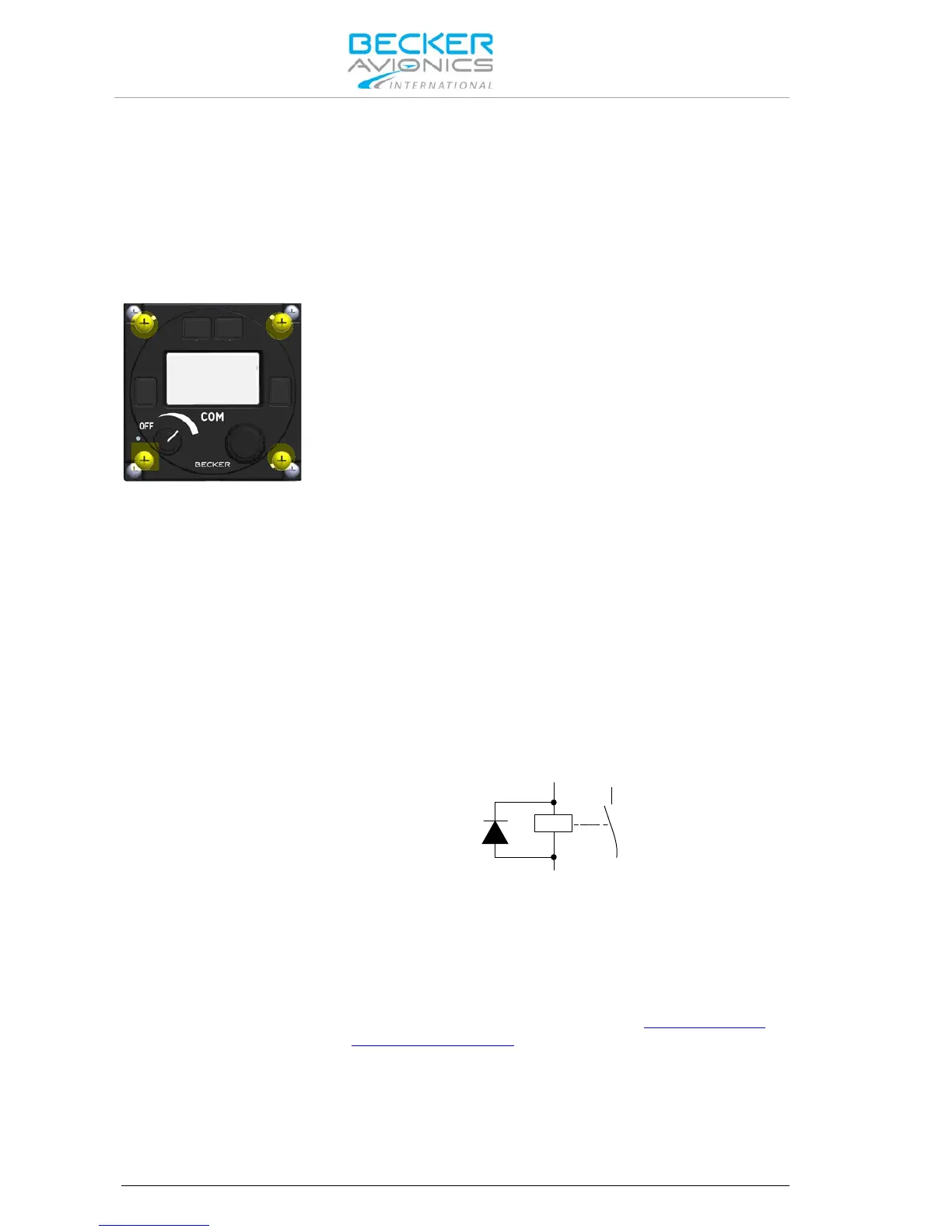
AR6201:
P1-24 = Power Indication (/PWR_EVAL)
This output indicates whether the transceiver is in "ON" or "OFF" status
by means of an open collector function. The output internally connects
to ground when the unit is "ON" and allow a current of maximum
100 mA to drive an external relay for example. The output shows high
impedance when the transceiver is "OFF".
Note: In order to avoid damage of this output a protection diode
in parallel to the external relay shall connected.
• If necessary modify the cable harness.
• Compare wiring requirements (see table "Pin Compatibility
AR4201 - AR6201" page 11).
For more details please refer to I&O manual:
http://www.becker-
avionics.com/downloads/ → AR620X Family