Replacement of the Transceiver
12 AR6201 Retrofit-Instructions Issue 01 November 2016
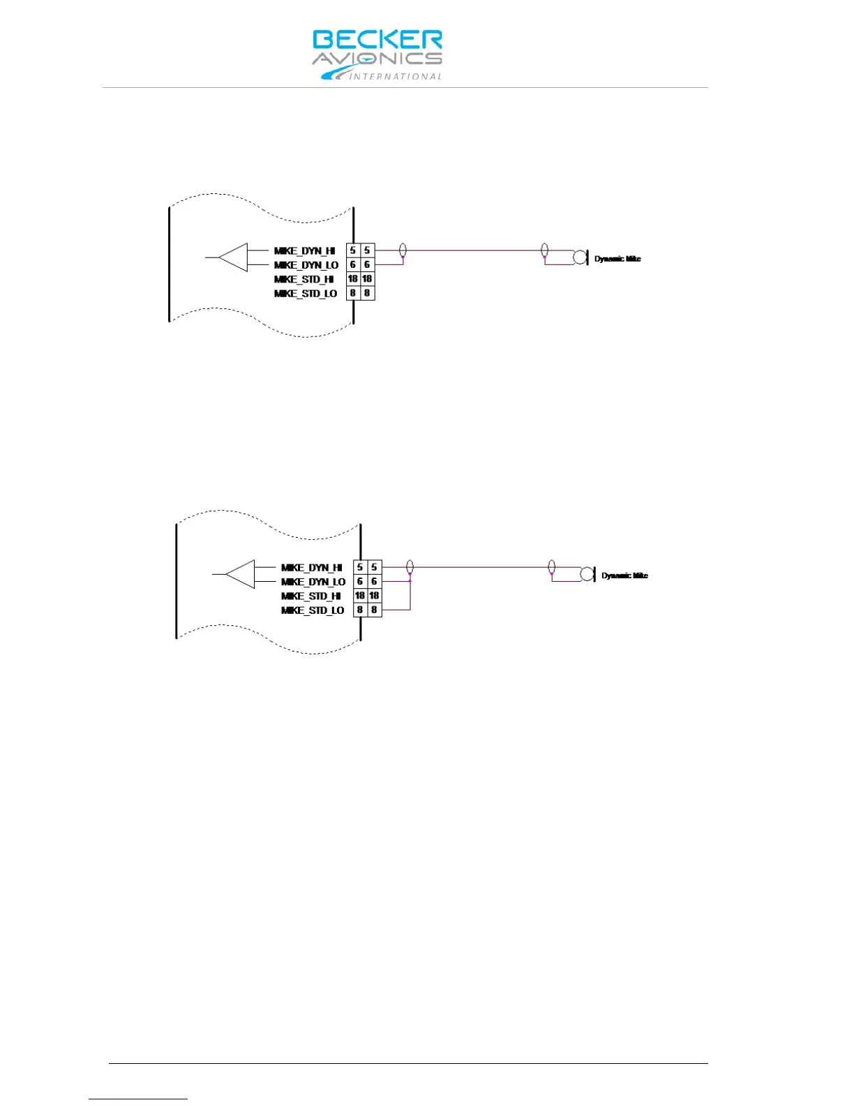
3.2.1. Dynamic Microphone Input
Retrofitting an AR4201 with the AR6201 in a typical glider installation with a dynamic microphone is
shown below:
Figure 3-1: AR6201 with Wiring Interface for AR4201
Connect the cable shielding to pin P1-6, which is the low side input for dynamic microphone. Because
in AR6201 this input is balanced, the cable shield is no longer connected to ground (unlike it was with
the AR4201). In most cases, it is not a problem.
If interference with the microphone signal does occur, it is recommended to carry out the following
modification:
Connect Pin P1-6 with Pin P1-8 (the cable shield is grounded). See Figure.
Figure 3-2: Modified Dynamic Microphone Wiring Interface for AR6201
3.2.2. Temperature Sensor
The AR6201 has no temperature sensor input. Remove wire from pin P1-8 and pin P1-20.
3.2.3. RS232 Interface
The AR6201 has no RS232 interface for remote control. Remove wire from pin P1-9 and pin P1-22.
3.2.4. AFCU/AGC/AFWB
Not used in aircraft installations, remove wire from pin P1-15 and pin P1-16.
3.2.5. CPIN (if Installed)
No influence in retrofit installation, please remove coding cap from the connector hole.
3.2.6. +13.75 V Switched (AR4201) - PWR_EVAL (AR6201)
The AR6201 provides on pin P1-24 a low signal when the unit is switched on and a high impedance
signal, when switched off.
Note: This is not compatible to the AR4201, which provided a positive power supply
when switched on and high impedance when switched off.
In cases where slave equipment needs to be switched ON/OFF in sync with the AR6201 connect a
relay to pin P1-24.