19
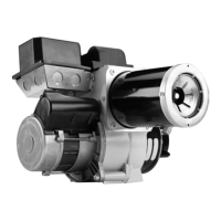
NX Burner Manual
Section: Perform Regular Maintenance
Removing Nozzle Line for Service
(Reference the Replacement Parts Diagram.)
Use only nozzles having the brand, fl ow rate (gph),
spray angle and pattern specifi ed by the appliance
manufacturer or Beckett Residential Burner OEM Spec
Guide, Part #6711.
Follow the appliance manufacturer’s specifi cations for
the required pump outlet pressure for the nozzle, since
this affects the fl ow rate.
Nozzle manufacturers calibrate nozzle fl ow rates at
100 psig.
This burner utilizes pressures higher than 100 psig,
so the actual nozzle fl ow rate will be greater than the
gph stamped on the nozzle body. (Example: A 1.00
gph nozzle @ 140 psig = 1.18 gph)
For typical nozzle fl ow rates at various pressures see
accompanying chart.
y
y
Incorrect nozzles and fl ow rates could
result in impaired combustion, under-
fi ring, over-fi ring, sooting, puff-back of
hot gases, smoke and potential fi re or
asphyxiation hazards.
Correct Nozzle and Flow
Rate Required
Before proceeding, turn off the main power switch
to the burner.
Remove the burner cover by loosening the four
thumb screws (two on each side of burner).
Disconnect the copper connector tube assembly
from the nozzle line bulkhead fi tting.
Loosen the two screws securing the igniter
retaining clips and rotate both clips to release the
igniter baseplate. The igniter should pop up and be
supported by the prop spring.
Loosen the two screws securing the rear door.
Swing the door to the right and down.
Loosen the splined nut.
Remove the nozzle line electrode and head
assembly from the burner by drawing it straight
back and out the rear door opening. The
adjustment mechanism is still attached. Be careful
not to damage the electrodes or insulators while
handling.
To replace the nozzle assembly, reverse the above
procedure.
1.
2.
3.
4.
5.
6.
7.
8.
Nozzle Installation
Perform the following steps when replacing a nozzle.
Use care when handling, removing and installing oil
nozzles.
Carefully follow the guidelines provided in this
section.
y
y
A damaged nozzle could cause impaired combustion,
sooting, puffback of hot gases, smoke, oil leakage
and potential fi re or asphyxiation hazards.
Protect Nozzle from
Damage
Remove the nozzle line assembly to gain access to
the nozzle.
Use a 3/4” open-end wrench to hold the nozzle
adapter. DO NOT attempt to remove or replace
the nozzle without securing the adapter, as nozzle
alignment could be seriously affected.
Do not squeeze the electrodes when handling the
nozzle line assembly. Excessive force could change
the electrode tip settings or damage the ceramic
electrode insulators.
1.
2.
3.
Table 8. Nozzle Flow Rate by Size
Nozzle fl ow rate U. S. gallons per hour of No. 2 fuel oil
when pump pressure (psig) is:
Nozzle
size
(rated at
100 psig)
125
psi
140 psi
(factory
std.)
150
psi
175 psi 200
psi
0.40 0.45 0.47 0.49 0.53 0.56
0.50 0.56 0.59 0.61 0.66 0.71
0.60 0.67 0.71 0.74 0.79 0.85
0.65 0.73 0.77 0.80 0.86 0.92
0.75 0.84 0.89 0.92 0.99 1.06
0.85 0.95 1.01 1.04 1.13 1.20
0.90 1.01 1.07 1.10 1.19 1.27
1.00 1.12 1.18 1.23 1.32 1.41
1.10 1.23 1.30 1.35 1.46 1.56
1.20 1.34 1.42 1.47 1.59 1.70
1.25 1.39 1.48 1.53 1.65 1.77
1.35 1.51 1.60 1.65 1.79 -
1.50 1.68 1.77 1.84 - -
1.65 1.84 - - - -
1.75 - - - - -

 Loading...