8
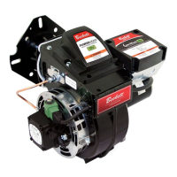
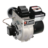
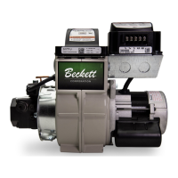
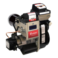
Mount Burner on Appliance
Mounting options
Table 4. Nozzle Flow Rate by Size
Nozzle fl ow rate U. S. gallons per hour of No. 2 fuel oil when
pump pressure (psig) is:
Nozzle
size
(rated at
100 psig)
125
psi
140
psi
150
psi
175
psi
200
psi
1.25 1.39 1.48 1.53 1.65 1.77
1.35 1.51 1.60 1.65 1.79 1.91
1.50 1.68 1.77 1.84 1.98 2.12
1.65 1.84 1.95 2.02 2.18 2.33
1.75 1.96 2.07 2.14 2.32 2.48
2.00 2.24 2.37 2.45 2.65 2.83
2.25 2.52 2.66 2.76 2.98 3.18
2.50 2.80 2.96 3.06 3.31 3.54
2.75 3.07 3.25 3.37 3.64 3.90
3.00 3.35 3.55 3.67 3.97 4.24
3.25 3.63 3.85 3.98 4.30 4.60
3.50 3.91 4.14 4.29 4.63 4.95
3.75 4.19 4.44 4.59 4.96 5.30
4.00 4.47 4.73 4.90 5.29 -
4.50 5.04 5.32 5.51 - -
5.00 5.59 ----
5.50 -----
Table 5. Nozzle Spray Angles
Recommended nozzle spray angles
“F” head 70°, 80° or 90° nozzle
Note: Always follow the appliance manufacturer’s nozzle specifi cation,
when available.
Figure 3. – Electrode Tip Adjustment
Bolt the burner to the appliance using the factory-
mounted fl ange or an adjustable fl ange.
Mounting dimensions
When using the Beckett universal adjustable fl ange,
mount the air tube at a 2° downward pitch unless
otherwise specifi ed by the appliance manufacturer.
Verify that the air tube installed on the burner
provides the correct insertion depth. See Figure 5.
The end of the air tube should normally be 1/4”
back from the inside wall of the combustion
chamber. Never allow the leading edge of the
head assembly to extend into the chamber, unless
otherwise specifi ed by the heating appliance
manufacturer. Carefully measure the insertion
depth when using an adjustable fl ange. Verify the
insertion depth when using a welded fl ange.
1.
2.
3.
Check/adjust electrodes
Check the electrode tip settings. Adjust if necessary
to comply with the dimensions shown in Figure 3. To
adjust, loosen the electrode clamp screw and slide/rotate
electrodes as necessary. Securely tighten the clamp
screw when fi nished.
Servicing nozzle line assembly
Turn off power to burner before proceeding.
Disconnect oil connector tube from nozzle line.
Loosen the two screws securing igniter retaining
clips and rotate both clips to release igniter
baseplate. Then tilt igniter back on its hinge.
Remove splined nut.
“F” head air tube. - Remove nozzle line assembly from
burner, being careful not to damage the electrodes
or insulators while handling. To ease removal of long
assemblies (over 9 inches), rotate assembly 180° from
installed position after pulling partially out of tube.
To replace the nozzle assembly, reverse the above
steps.
1.
2.
3.
4.
5.
6.
Check/Adjust ‘Z’ Dimension - ‘F’ Heads
See Figure 4 for complete details.
Section: Mount Burner on Appliance
Do Not use Adjustable
Mounting Flange on Mobile
Units
The shock and vibration could cause loss of burner
alignment and insertion problems resulting in fl ame
impingement, heavy smoke, fi re and equipment
damage.
Only use specifi ed factory-welded fl ange and air
tube combinations.
y
 Loading...