Product Description
Product Description
Appropriate Use
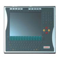
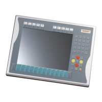
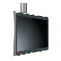
The CP70xx Control Panel is designed for industrial application in machine
and plant engineering. An aluminum housing contains a TFT display,
touch-screen/pad (optional), and a PC keyboard (optional). The panel is
installed via the 4 mounting holes in the backplane or the mounting arm
system adapter (optional).
Do not use the Control
Panel in areas of explosive
hazard
The Control Panel must not be used where there is a risk of
explosion.
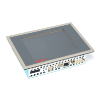
Connections
Control Panel CP70xx
connections
Pin assignment
Pin Signal Pin Signal
1
RXD
2
GND
CP-Link A
Data
BNC-connector
CP-Link
Pin Signal Pin Signal
1
TXD,
Power
supply
2
GND
CP-Link B
Data, Power supply
BNC-connector
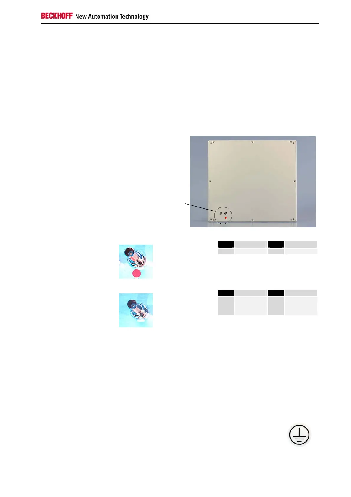
Connector description
CP-Link connection
CP-Link
The CP-Link connection allows data transmission between Control Panel
and CP-Link-Interface card of the Industrial-PC and providing the Control
Panel with the supply voltage. Two coaxial cables are required, the cable
length between Control Panel and Industrial-PC amounts to at most 100 m.
The red point on the CP-Link card and the red marking at the coaxial cable
or at the bend protection allow better orientation while connecting the
system.
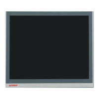
Protective Earthing
Protective Earthing
The low resistance protective earthing connection is
established via the ground bolt, which is located at the rear of
the housing.
CP70xx 5
 Loading...