EasyManuals Logo

Beckhoff EK1100 User Manual

Beckhoff EK1100
85 pages
To Next Page IconTo Next Page
To Previous Page IconTo Previous Page
Page #63 background imageLoading...
Page #63 background image
Commissioning/application notes
EK110x, EK15xx 63Version: 3.6
2. Attaching the connector
Push the two cable ends into the connector and the connector back until it stops. The fibers should now
protrude no more than 1.5mm from the front openings.
Close the connector by folding the upper and lower halves together until they engage.
Fig.44: Cable inserted in the connector
Fig.45: Closed connector
When inserting the wires into the connector ensure the optical channels are crossed (Tx1 → Rx2; Tx2 →
Rx1). The 'nose' at the connector hinge can be used as a guide.
Fig.46: Correctly connected optical channels

Table of Contents

Questions and Answers:

Question and Answer IconNeed help?

Do you have a question about the Beckhoff EK1100 and is the answer not in the manual?
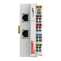
Beckhoff EK1100 Specifications

General IconGeneral
Product TypeEtherCAT Coupler
Number of Ports2
FieldbusEtherCAT
Bus InterfaceEtherCAT
Protection ClassIP20
Max. Current Supply for the E-bus2 A
Electrical Isolation500 V (E-bus/Fieldbus)
Weightapprox. 150 g
Relative Humidity95%, no condensation
Vibration/Shock ResistanceConforms to EN 60068-2-6/EN 60068-2-27
EMC Immunity/EmissionConforms to EN 61000-6-2/EN 61000-6-4
Approvals/MarkingsCE, UL, ATEX, IECEx
Power Supply24 V DC (-15%/+20%)
Operating Temperature-25°C to +60°C
Storage Temperature-40°C to +85°C
Current Consumption Power Contacts10 mA
Number of I/O Modules64
Installation Positionany

Related product manuals