Product overview
EL28xx-xxxx 19Version: 2.2
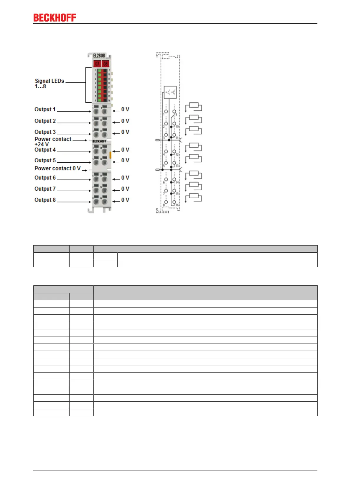
2.1.3 Pin assignment and LEDs
Fig.13: EL2808
EL2808 - LEDs
LED Color Meaning
OUTPUT 1- 8 green off No output signal
on 24V
DC
output signal at the respective output
EL2808 - pin assignment
Terminal point Description
Name No.
Output 1 1 Output 1
Output 2 2 Output 2
Output 3 3 Output 3
Output 4 4 Output 4
Output 5 5 Output 5
Output 6 6 Output 6
Output 7 7 Output 7
Output 8 8 Output 8
0V 9 0 V (internally connected to terminal point 10, 11, 12, 13, 14, 15, 16 and negative power contact)
0V 10 0 V (internally connected to terminal point 9, 11, 12, 13, 14, 15, 16 and negative power contact)
0V 11 0 V (internally connected to terminal point 9, 10, 12, 13, 14, 15, 16 and negative power contact)
0V 12 0 V (internally connected to terminal point 9, 10, 11, 13, 14, 15, 16 and negative power contact)
0V 13 0 V (internally connected to terminal point 9, 10, 11, 12, 14, 15, 16 and negative power contact)
0V 14 0 V (internally connected to terminal point 9, 10, 11, 12, 13, 15, 16 and negative power contact)
0V 15 0 V (internally connected to terminal point 9, 10, 11, 12, 13, 14, 16 and negative power contact)
0V 16 0 V (internally connected to terminal point 9, 10, 11, 12, 13, 14, 15 and negative power contact)