List of illustrations
KL2xxx and KS2xxx38 Version: 3.0.0
List of illustrations
Fig. 1 KL2012 – 2-channel digital output terminal, 24 VDC, 0.5 A ........................................................ 8
Fig. 2 KL2022 – 2-channel digital output terminal, 24 VDC, 2 A ........................................................... 9
Fig. 3 KL2032 – 2-channel digital output terminal, 24 VDC, 0.5 A, protected against reverse polarity
connection ................................................................................................................................... 9
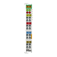
Fig. 4 KL2012 - LEDs and connection ................................................................................................... 11
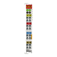
Fig. 5 KL2022 - LEDs and connection ................................................................................................... 12
Fig. 6 KL2032 - LEDs and connection ................................................................................................... 13
Fig. 7 KL2114 – 4-channel digital output terminal, 24 VDC, 0.5 A ........................................................ 14
Fig. 8 KL2134 – 4-channel digital output terminal, 24 VDC, 0.5 A, protected against reverse polarity
connection ................................................................................................................................... 14
Fig. 9 KL2114 - LEDs and connection ................................................................................................... 16
Fig. 10 KL2134 - LEDs and connection ................................................................................................... 17
Fig. 11 KL2404 – 4-channel digital output terminal, 24 VDC, 0.5 A ........................................................ 18
Fig. 12 KL2404 – 4-channel digital output terminal, 24 VDC, 2 A ........................................................... 18
Fig. 13 KL2404 - LEDs and connection ................................................................................................... 20
Fig. 14 KL2424 - LEDs and connection ................................................................................................... 21
Fig. 15 KL2408 – 8-channel digital output terminal, 24 VDC, 0.5 A ........................................................ 22
Fig. 16 KL2488 – 8-channel digital output terminal, 24 VDC, 0.5 A, ground switching ........................... 22
Fig. 17 KL2408 – 8-channel digital output terminal, 24 VDC, 0.5 A ........................................................ 24
Fig. 18 KL2488 – 8-channel digital output terminal, 24 VDC, 0.5A, ground switching ........................... 25
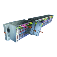
Fig. 19 Attaching on mounting rail ........................................................................................................... 26
Fig. 20 Disassembling of terminal............................................................................................................ 27
Fig. 21 Power contact on left side............................................................................................................ 28
Fig. 22 Standard wiring............................................................................................................................ 30
Fig. 23 Pluggable wiring .......................................................................................................................... 30
Fig. 24 High Density Terminals................................................................................................................ 30
Fig. 25 Mounting a cable on a terminal connection ................................................................................. 31