8
25
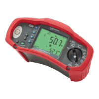
Indicates the preset fault voltage limit. The default setting is 50 V. Some
locations require the fault voltage be set to 25 V, as specified by local electrical
codes. Press F4 when you turn on the tester to toggle the fault voltage
between 25 V and 50 V. The value you set will appear on the display and will be
saved when you turn the tester off.
26 Primary display and measurement units.
27
Low battery icon. See “Testing and Replacing the Batteries” section for
additional information on batteries and power management.
28 Appears when you press the Test button. Disappears when the test is completed.
29
Appears when the instrument is overheated. The Loop test and RCD functions
are inhibited when the instrument is overheated.
30
Appears when an error occurs. Testing is disabled. See “Error Codes” on page 9
for a listing and explanation of possible error codes.
31
Name of the secondary measurement function.
U
N
Test voltage for insulation test.
U
F
Fault voltage. Measures neutral to earth.
PSC
Prospective Short Circuit. Calculated from measured voltage and impedance
when reading line to neutral.
PEFC
Prospective Earth Fault Current. Calculated from voltage and loop impedance
which is measured line to protective earth.
I
K
In combination with the PSC or PEFC symbol, indicates a short circuit current.
R
E
Earth resistance.
32
Secondary display and measurement units. Some tests will return more than
one result or return a computed value based on the test result. This will occur
with:
• Volts
Secondary display shows line frequency.
• Insulation tests
Secondary display shows actual test voltage.
• Loop/line impedance
Secondary display shows PEFC (Prospective Earth Fault Current) or R
E
PSC
(Prospective Short Circuit Current).
• RCD switching time
Secondary display shows U
F
fault voltage.
• RCD tripping current
Secondary display shows U
F
fault voltage.
33
Appears only in Volts. For more information see “Testing and Replacing the
Batteries” Section.
34
Appears when you press the button to zero the leads. After the zeroing
operation, the icon stays illuminated indicating that zeroing has been
performed. Only used when performing continuity or loop testing.
35 Potential danger. Appears when measuring or sourcing high voltages.