12
Measuring Continuity
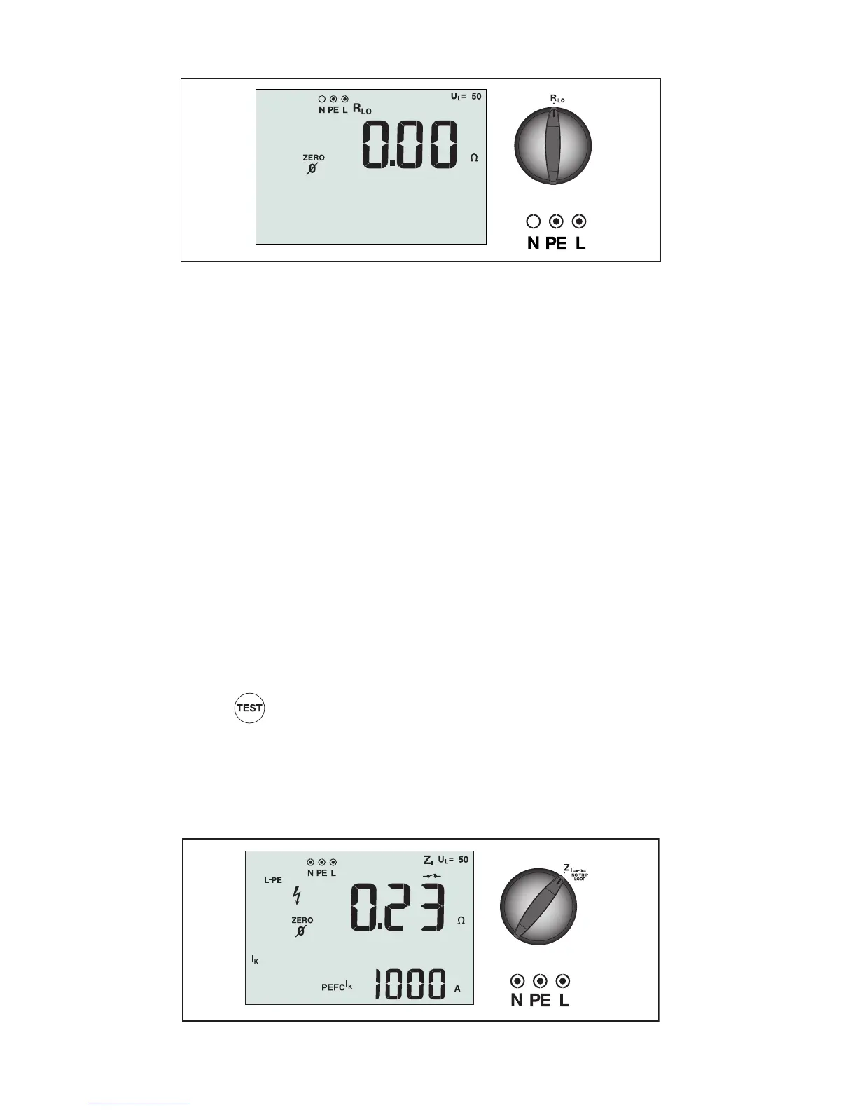
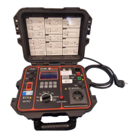
Figure 5. Continuity Zero Display/Switch and Terminal Settings
A continuity test is used to verify the integrity of connections by making a high resolution
resistance measurement. This is especially important for checking Protective Earth
connections.
Note: In countries where electrical circuits are laid out in a ring, it is recommended that you
make an end-to-end check of the ring at the electrical panel.
WWarning
• Measurements should only be performed on de-energized circuits.
• Measurements may be adversely affected by impedances or parallel circuits or transient
currents.
To measure continuity:
1. Turn the rotary switch to the RLO position.
2. Use the L and PE (red and green) terminals for this test.
3. Before making a continuity test, use the Zero adapter to zero the test leads. Press and
hold until the ZERO annunciator appears. The tester measures probe resistance,
stores the reading in memory, and subtracts it from readings. The resistance value is
saved even when power is turned off so you don’t need to repeat the operation every
time you use the instrument.
Note: Be sure the batteries are in good charge condition before you compensate the
test leads.
4. Press and hold
until the reading settles. If the continuity beeper is enabled, the
tester beeps continuously for measured values less than 2 Ω and there is no stable
reading beep for measured values 2 ohms or greater. If a circuit is live, the test is
inhibited and the AC voltage appears in the secondary (lower) display.
Measuring Loop/Line Impedance
Figure 6. Loop/Line Impedance/Switch and Terminal Settings