31
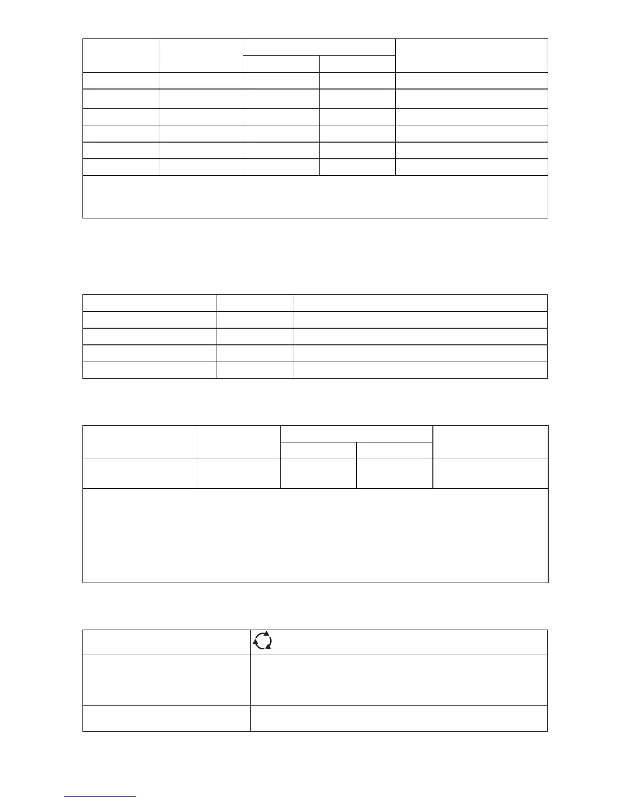
Current
Multiplier
*RCD Type
Measurement Range
Trip Time Accuracy
Europe UK
X ½ G 310 ms 2000 ms ± (1% Reading + 1ms)
X ½ S 510 ms 2000 ms ± (1% Reading + 1ms)
X 1 G 310 ms 310 ms ± (1% Reading + 1ms)
X 1 S 510 ms 510 ms ± (1% Reading + 1ms)
X 5 G 50 ms 50 ms ± (1% Reading + 1ms)
X 5 S 160 ms 160 ms ± (1% Reading + 1ms)
Note:
*G – General, no delay
*S – Time delay
Maximum Trip Time
The RCD √ symbol switches on when testing the RCD trip time if the trip time meets the
following conditions:
RCD I
P
N
Trip Time Limits
AC G, A X 1 Less than 300 ms
AC G-S, A-S X 1 Between 130 ms and 500 ms
AC G, A X 5 Less than 40 ms
AC G-S, A-S X 5 Between 50 ms and 150 ms
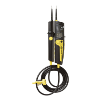
RCD/FI-Tripping Current Measurement/Ramp Test ( I
P
N
)
Current Range Step Size
Measurement Range
Measurement
Accuracy
Type G Type S
30 % to 110 % of
RCD rated current
[1]
10 % of I
PN
300 ms/step 500 ms/step ±5 %
Notes
[1] 30 % to 150 % for Type A I
PN
>10 mA
30 % to 210 % for Type A I
PN
= 10 mA
Specified trip current ranges (EN 61008-1):
50 % to 100 % for Type AC
35 % to 140 % for Type A (>10 mA)
35 % to 200 % for Type A (≤10 mA)
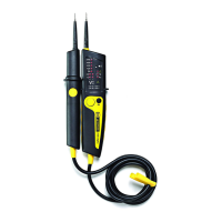
Phase Sequence Indication
Icon
icon Phase Sequence indicator is active.
Display of Phase Sequence Displays “1-2-3” in digital display field for correct
sequence. Displays “3-2-1” for incorrect phase. Dashes in
place of a number indicate a valid determination could
not be made.
Mains Input Voltage Range
(phase-to-phase)
100 to 500 V