12
2. CONTROL ELEMENTS AND
CONNECTORS
This chapter describes the various control elements of your
DDX3216. Analog controls and connectors will be discussed in
full detail.
2.1 Connection interfaces and control elements
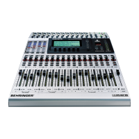
on the top side of the DDX3216
The connectors and controls for the analog inputs are located
in the upper section of the DDX3216. Ex factory, the analog
inputs are assigned to channels 1-16.
2.1.1 Microphone and line inputs 1-12
The inputs 1-12 are mic/line inputs and have analog insert
points (ISR = Insert Send Return).
Fig. 2.1: Connectors and controls of analog mic/line inputs
MIC
The microphone inputs are on balanced XLR connectors and
feature a switchable phantom power supply for condenser mics
(cf. chapter 2.1.3 “Phantom power and 2-track inputs/outputs”).
LINE IN
The line inputs are on balanced 1/4" TRS connectors and
function in parallel to the microphone inputs.
INSERT
The insert points are on 1/4" TRS connectors (tip = send, i. e.
connection with input of external device; ring = return, i. e.
connection with output of external device; shaft = ground, cf.
chapter 17.2.1 “Analog connections”). In this way, you can insert
analog signal processing devices before the channel’s A/D
converters. Use commercially available insert cables (1/4" TRS
on 2 x 1/4" phone connectors) for this connection. Insert points
are very useful when you need to process channel signals with
dynamic processors or equalizers. The insert points can also be
used as tape sends to a multi-track recorder.
PAD
This attenuation switch (PAD) for line-level signals (or
microphones with very high output levels) reduces the input
gain by 20 dB.
SIG and CLIP LEDs
These LEDs monitor the analog signal level after the insert point.
When gain ist closed, the SIG LED lights at approx. -46 dBu (mic)/
-23 dBu (line) indicating the presence of audio. The CLIP LED
lights at approx. 0 dBu (mic)/+23 dBu (line) and warns you of
signal distortion.
+ Make sure that the CLIP LED does not light up.
GAIN
Use the GAIN control to adjust the mic/line input signal gain.
The setting range is from +10 dB to +60 dB for the XLR input, and
from -10 dB to +40 dB for the 1/4" TRS input.
2.1.2 Line inputs 13 to 16
Inputs 13-16 are on balanced 1/4" TRS connectors and can be
used for line-level signals only.
Fig. 2.2: Connectors and controls for inputs 13-16
LINE IN
The line inputs are on balanced 1/4" TRS connectors.
SIG and CLIP LEDs
These LEDs monitor the analog signal level after the insert
point. When gain is in center position, the SIG LED lights at approx.
-36 dBu (unity gain) indicating the presence of audio. The CLIP
LED lights at approx. +10 dBu (unity gain) and warns you of
signal distortion.
GAIN
Use the GAIN control to adjust the line input signal gain. The
setting range is from -20 dB to +20 dB.
+ On the S/PDIF page in the I/O menu, you can assign
the inputs of channels 13/14 to the digital S/PDIF
input. When S/PDIF is selected as the signal source
for channels 13/14, the “normal” channel input
signals are replaced by the signals present at the
digital S/PDIF input.
2.1.3 Phantom power and 2-track inputs/outputs
Fig. 2.3: Phantom power and 2-track inputs/outputs
The +48 V phantom power required for condenser mics can
be activated separately for channels 1-6 and 7-12. The
associated switches light up when phantom power is on.
CH. 1-6
This switch activates the phantom power supply for microphone
channels 1-6.
CH. 7-12
This switch activates the phantom power supply for microphone
channels 7-12.
+ Please mute your audio system before you activate
the phantom power supply, so as to prevent switch-
on thumps from being passed on to your monitor
speakers and/or headphones.
2. CONTROL ELEMENTS AND CONNECTORS

 Loading...
