13
TAPE IN
These RCA connectors (nominal level: -10 dBV) are used to
return the signals from a stereo master recorder.
+ Press the 2 TK TO CTRL R switch to monitor the
TAPE INPUTS via the control room and/or phones
outputs.
TAPE OUT
These RCA connectors are wired in parallel to the MAIN OUT
and provide the main mix signal with a nominal level of -10 dBV
(unbalanced).
TO CH 15/16
This switch sends the signal present at the TAPE IN connectors
to channels 15/16, and disables line inputs 15/16.
2.1.4 Control room and phones sections
Fig. 2.4: Control room and phones sections
2 TK TO CTRL R
Press this switch to route the signal applied to the TAPE IN to
the control room and phones outputs.
LEVEL (control room)
This LEVEL control adjusts the control room output level.
+ You can also select other signals in the MONITOR
menu (see chapter 6.1 ”MONITOR menu”) and route
them to the control room output.
PHONES connector
Connect your headphones to this 1/4" TRS connector. The
PHONES signal and the CONTROL ROOM signal are identical.
LEVEL (phones)
This LEVEL control determines the headphones volume and
works independently of the control room LEVEL control.
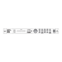
2.2 The rear panel of the DDX3216
2.2.1 Control room, multi and main outputs
Fig. 2.5: Control room, multi and main outputs
CONTROL ROOM OUTPUTS
Normally, the control room output is connected to the monitor
system set up in the control room and provides the stereo main
mix or specific solo signals. The outputs are on balanced 1/4"
TRS connectors with a nominal level of +4 dBu.
MULTI OUTPUTS
The MULTI outputs can carry any of the 28 bus signals in your
DDX3216, i. e. aux outputs, FX sends, stereo main mix, stereo
solo bus or one of the 16 master bus signals. The outputs must
be assigned accordingly on the MULTI page in the I/O menu
(default: aux sends 1-4). The MULTI outputs are on balanced
1/4" TRS connectors with a nominal level of +4 dBu.
MAIN OUTPUTS
The MAIN outputs provide the MAIN MIX signal and are on
balanced XLR connectors with a nominal level of +4 dBu.
2.2.2 Digital S/PDIF and wordclock inputs/outputs
Fig. 2.6: Digital S/PDIF and wordclock inputs/outputs
DIGITAL COAXIAL OUT
The digital coaxial output (RCA) provides the MAIN MIX signal
in a digital S/PDIF format. The parameters word length and dither
for the digital output can be adjusted on the S/PDIF page in the I/O
menu.
DIGITAL COAXIAL IN
This RCA connector allows you to feed in S/PDIF signals, with
a sampling rate between 32 and 50 kHz. The input is fitted with
a sample rate converter, so as to be able to feed in digital signals
with a sample rate other than that used by the DDX3216.
The S/PDIF input can be routed exclusively to channels 13/14,
replacing the input signal connected to these inputs (see S/PDIF
in I/O menu).
If the DDX3216 is operated via its digital connectors, all digital
devices connected to the console must be synchronized to a
common wordclock rate. With an (optionally available) I/O module
installed and devices such as digital multi-track recorders
connected via digital leads, one of these devices must be defined
as the wordclock master providing the clock rate for all other
units. For this purpose, the DDX3216 generates internal clock
rates of 44.1 or 48 kHz. In slave mode the console can be clocked
via its wordclock input or from an device connected to an I/O
module. The wordclock signal source is adjusted on the
FS CLOCK page in the SETUP menu.
Wordclock signals are usually distributed in a network
configuration, i. e. using 75-Ω coaxial cables, BNC-T adapters
and terminating resistors.
WORDCLOCK OUT
The word clock output is on a BNC connector and provides a
wordclock signal with the sample rate used by the console (TTL
level square wave).
WORDCLOCK IN
The wordclock Input is on a BNC coaxial connector and accepts
wordclock signals between 40 and 50 kHz.
+ If you encounter problems with the reception of
word clock signals, you can connect a 75-ohm
resistor to the wordclock input of the DDX3216.
2.2.3 SMPTE and RS232 inputs
Fig. 2.7: SMPTE and RS232 inputs
SMPTE INPUT
The timecode input (XLR-3) accepts SMPTE timecode signals
for the control of the console’s dynamic automation. Usually, such
signals are provided by a computer, video or multi-track recorder.
The frame rate and incoming timecode are displayed on the SETUP
pages in the MIDI and DYNAMIC AUTOMATION menus.
RS232 I/O
The 9-pin RS232 connector enables the DDX3216 to communi-
cate with a computer. For example, you can save and load files,
or update the DDX3216 operating system.
Of course, you will find an appropriate serial cable (1:1) for
the connection to the serial interface of your personal computer
included with your DDX3216.
2. CONTROL ELEMENTS AND CONNECTORS