14
2.2.4 MIDI connections
Fig. 2.8: MIDI connections
The MIDI connectors on the rear of the console are on
internationally standardized 5-pin DIN jacks. Use MIDI cables to
connect your DDX3216 to other MIDI equipment. Such cables are
commercially available, their length should not exceed 50 feet.
The data are transmitted via electrically isolated optocouplers.
MIDI IN: use this input to receive MIDI control data.
MIDI THRU: this connector provides an identical copy of the
MIDI signal received at the MIDI IN jack.
MIDI OUT: use this output to transmit data to a connected
computer or other MIDI equipment.
2.2.5 Power supply and fuse
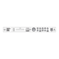
Fig. 2.9: Power supply and fuse
POWER switch
Use the POWER switch to turn the DDX3216 on and off.
FUSE HOLDER
Use the enclosed IEC power cord to connect the unit to the
mains. It complies with all applicable safety standards. Blown
fuses must always be replaced by fuses of the same type and
rating.
IEC MAINS CONNECTOR
Use this mains connector and the enclosed power cord to
connect the unit to the mains.
SERIAL NUMBER
Please take the time to fill in and return the warranty card
within 14 days after the date of purchase, so as to benefit from
our extended warranty. Or use our online registration option
available on the World Wide Web at www.behringer.com.
2.2.6 Option slots 1 and 2
Fig. 2.10: Option slots 1 and 2
These two option slots allow you to expand your DDX3216 by
means of two optionally available expansion cards, which are
equipped with various digital connectors (AES/EBU, ADAT
®
and
TDIF).
Fig. 2.10 shows a TDIF module installed in slot 1. The second
slot is not in use and has a blank panel attached.
+ A detailed installation manual is enclosed with each
optionally available expansion card.
2.3 PCMCIA card slot
Fig. 2.11: PCMCIA card slot
The PCMCIA card slot is used to exchange data between the
DDX3216 and a PC card equipped with a flash memory.
+ Only use PC cards of the “5 V ATA Flash Card” type
(any memory capacity permitted).
2.4 Channels and main mix
The DDX3216 features 16 identical channel strips controlling all
of the 32 inputs, 16 master busses, four aux and four FX sends
as well as eight returns from the built-in effects devices. For this
purpose, your DDX3216 has four fader banks with 16 channels
each. The MAIN fader always controls the stereo main mix.
Fader bank Channels
CH 1-16 Channels 1 to 16
CH 17-32 Channels 17 to 32
BUS OUT 1-16 Busses 1 to 16
AUX/FX Aux/FX sends and FX returns
Tab. 2.1: Four fader banks and associated channels
2.4.1 Channel strips
Fig. 2.12: Channel strip
Each of the 16 channel strips has the following firmly assigned
control elements:
Channel fader
The channel faders are 100-mm motorized faders made by
ALPS
®
. Their function depends on what is selected in the fader
banks.
2. CONTROL ELEMENTS AND CONNECTORS