31
Buzz-Gain (0 to 100%)
The Buzz-Gain parameter determines the volume of the hum
noise generated.
Noise-LP (200 Hz to 20 kHz)
This parameter adjusts the cutoff frequency of a low-pass
filter, which is effective exclusively on the noise generated by
the LoFi algorithm.
Buzz-Freq (50/60 Hz)
This parameter adjusts the frequency of the hum noise.
5.2.26 Ring Modulator
This effect allows you to shape audio signals quite drastically.
Similar to medium wave radio, the signal is multiplied by a carrier
frequency. The resulting effect is ideal for “robot voices”, etc.
Fig. 5.27: Parameters of Ring Modulator algorithm
Mod.-Mode (Tri, Sin, Squ or Env)
This parameter controls the shape of the modulating waveform
(triangle, sine, square or envelope).
Mod.-Depth (0 to 100%)
Mod.-Depth controls the modulation depth, i. e. the amplitude
of the modulating oscillation. High values produce a more
pronounced effect.
LFO Speed (0.1 to 100 Hz)
The LFO Speed parameter adjusts the speed (frequency) of
the modulating signal.
Env-Response (10 to 1,000 ms)
Defines the envelope attack and release times.
AM-Carrier-Freq (100 Hz to 10 kHz)
Use this parameter to adjust the carrier frequency.
AM-Depth (0 to 100%)
The AM-Depth parameter determines the AM modulation depth.
Bandlimit (100 Hz to 20 kHz)
Use this parameter to adjust the cutoff frequency of a
subsequent low-pass filter used to cut “hard” high-frequency
content.
6. MONITOR SECTION AND LEVEL
METERS
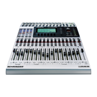
The DDX3216 gives you powerful monitoring features, such
as a dedicated solo bus, which allows you to monitor the soloed
PFL or AFL signal of the input channels or all aux and bus outputs.
What is more, you can monitor almost any input or output via the
control room and/or phones outputs.
The control room output is usually connected to the monitoring
system, and normally carries the stereo main mix or solo signals.
Its outputs are on balanced 1/4" TRS connectors with a nominal
level of +4 dBu, but can also be used with unbalanced
connectors. The output level is controlled with the CONTROL
ROOM LEVEL potentiometer. The MON -20 dB switch in the MAIN
strip can be used to reduce the level at the control room or
phones output by 20 dB.
+ Please note that this switch is not effective on the
2-track signal.
The 2 TRACK TAPE IN connectors allow you to return the
signals from a stereo recorder and play them back via the
control room and/or phones outputs. They are on RCA connectors
with a nominal level of -10 dBV.
Enable the 2 TK TO CTRL R switch to monitor the 2 TRACK
TAPE IN via the control room bus and phones outputs.
The signal applied to the 2 TRACK IN can be routed to input
channels 15/16 with the TO CH 15/16 switch.
The PHONES output basically carries the same signal as the
control room output. The headphones volume can be adjusted
independently of the control room level with the associated LEVEL
control.
6.1 MONITOR menu
Fig. 6.1: MONITOR menu
Press the MONITOR switch in the left switch block to display
the MONITOR menu, in which you can determine the signals to
be sent to the control room and/or phones outputs. You can also
adjust the solo level and set the solo function from PFL to AFL,
and vice versa. PFL (pre-fader listen) is pre-fader and pan, AFL
(after-fader listen) is after-fader and pan.
6.1.1 Mono/stereo switching
The left master controller in the MONITOR menu controls the
mono/stereo switching. This function is particularly useful to
position and align two stereo speakers (in MONO mode, the
signal source must be located precisely between the two
speakers), to isolate specific signals, or to check a mix for its
mono compatibility.
The following options are available:
Stereo
The selected signal source is monitored in stereo.
Mono L
The left channel of the selected signal source is sent at equal
levels to both channels of the control room output.
Mono R
The right channel of the selected signal source is sent at equal
levels to both channels of the control room output.
6. MONITOR SECTION AND LEVEL METERS

 Loading...
