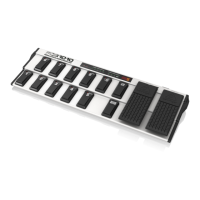
Controls
1. FOOTSWITCHES 1 through 10/0. These keys are used for changing the presets, programming, entering values in
programming mode and activating the DIRECT SELECT function (10/0 only).
2. UP/DOWN keys. These keys are used to navigate through different banks and programming layers. When in programming
mode, use the UP key for ENTER (confirm) and the DOWN key for ESCAPE (cancel).
3. EXPRESSION PEDAL A. Allows you to change controller values continuously. In programming mode, the pedal is used for
data entry.
4. EXPRESSION PEDAL B. Allows you to change controller values continuously.
5. STATUS LEDs. The yellow LEDs display the current status of the PRESET programming or GLOBAL CONFIGURATION
functions.
6. LED DISPLAY. Informs you about the currently selected BANK/PRESET number. In programming mode, it displays any value
changes.
7. FUSE HOLDER / VOLTAGE SELECTOR.
8. IEC POWER CONNECTOR.
9. Use the POWER switch to power up your FCB1010. Always make sure the POWER switch is in its “Off” setting when you
connect the FCB1010 to the mains.
10. SERIAL NUMBER.
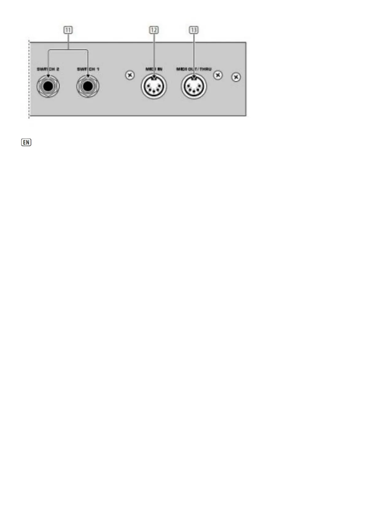
11. SWITCH 1 and 2. Use these jacks to connect your amplifier for channel selection (mono or stereo phone jack cable).
12. MIDI IN. The MIDI IN of your FCB1010 connects to a sequencer or similar device, in order to download the memory data
saved before with the help of the MIDI SysEx function. Additionally, data can be looped through the FCB1010 and merged with
other data using the MIDI MERGE function. Subsequently, the combined data are available at the MIDI OUT/THRU connector.
13. MIDI OUT/THRU. Use this jack to connect the devices you wish to control from your FCB1010. The SOFT THRU circuit allows
you to loop through any signals present at the MIDI IN of your FCB1010, merge them with the unit’s own data stream, and
finally output the combined data at the MIDI OUT.
Specifications