14. RATE – Controls the rate of the SAMPLE AND HOLD clock.
15. GLIDE – Sets the rate of change between sample values.
SLEW RATE LIMITER
16. SLEW – limits the rate of change of the input signal.
17. PORTA TIME – Controls the rate of change between midi notes.
ATTENUATOR SECTION
18. ATTENUATOR 1 – Used to reduce the amplitude of the input signal. ATT1 can be controlled by a control
voltage. See 58.
19. ATTENUATOR 2 – Reduces the amplitude of a signal.
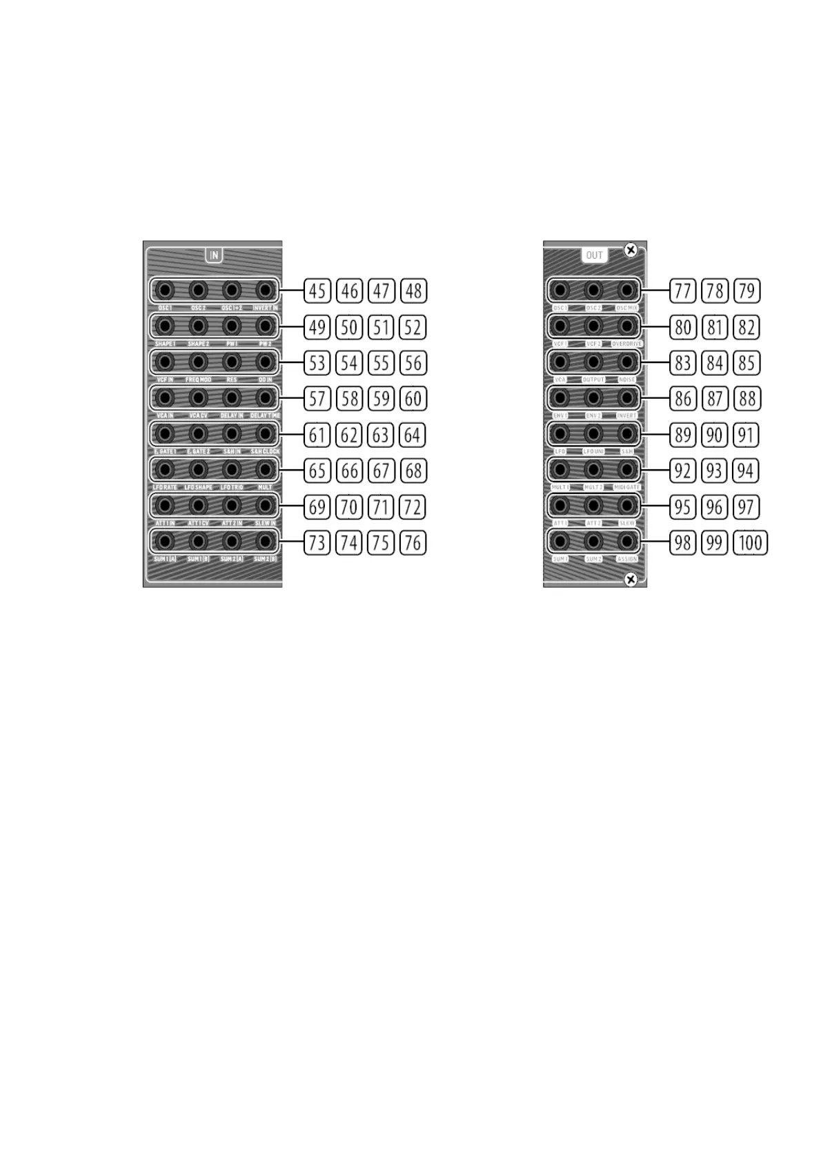
INPUT PATCH BAY SECTION
20. OSC 1 –OSC 1 pitch CV.
21. OSC 2 – OSC 2 pitch CV.
22. OSC1+2 – OSC 1 and 2 pitch CV.
23. INVERT IN – The input signal is inverted at INVERT OUT. See 88.
24. SHAPE 1 – OSC 1 Shape CV.
25. SHAPE 2 – OSC 2 Shape CV.
26. PW1 – OSC 1 PW CV.
27. PW2 – OSC 2 PW CV.
28. VCF – VCF signal input.
29. FREQ MOD – VCF cutoff frequency CV.
1. RES – VCF resonance CV.
2. OD IN – Overdrive signal input.
3. VCA IN – VCA signal input.
4. VCA CV – VCA CV.
5. DELAY IN – Delay signal input.
6. DELAY TIME – Delay time CV.
7. E.GATE1 – Envelope 1 gate.
8. E.GATE2 – Envelope 2 gate.
9. S&H IN – Sample and Hold signal input.
10. S&H CLOCK –Sample and Hold clock input.
11. LFO RATE – LFO Rate CV.
12. LFO SHAPE – LFO Shape CV.
13. LFO TRIG – LFO Trigger input.
14. MULT – MULT signal input. See 92/93.
15. ATT1 IN – Attenuator 1 signal input.

 Loading...