9
E
The mains connection of the ULTRAMIZERPRO is made by using the supplied cable. It meets all of the
international safety certification requirements. Please make sure that all units have a proper ground connec-
tion.
+ Before you connect your ULTRAMIZERPRO to the mains, please make sure that your local
voltage matches the voltage required by the unit (see chapter 5.2 for details)!
As a standard the audio inputs and outputs on the BEHRINGER ULTRAMIZERPRO are fully balanced. If
possible, connect the unit to other devices in a balanced configuration to allow for maximum interference
immunity. The automatic servo function detects unbalanced connections and compensates the level differ-
ence automatically (6dB correction).
The MIDI links (IN/OUT/THRU) are made over standardized DIN patch cords. The data communication is
isolated from ground by an opto-coupler.
1.3 Control elements
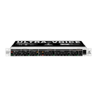
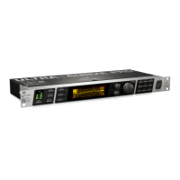
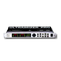
Fig. 1.1: ULTRAMIZERPRO front panel
The BEHRINGER ULTRAMIZERPRO is equipped with ten illuminated parameter keys, one jog wheel (rotary
control), a numeric display, 8 LED indicators and a power switch. Each of the two fully independent channels
can be monitored with four 8-stage LED meters, displaying input level, output level and gain reduction for both
bands.
1.3.1 Front panel
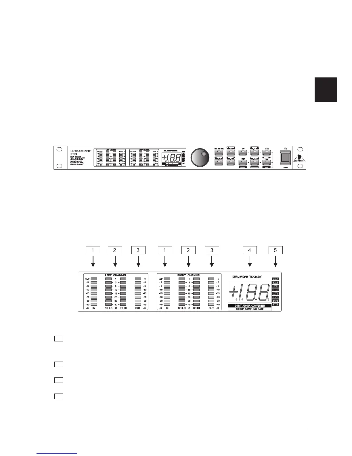
Fig. 1.2: Display section DSP1400P
1
The two LED chains read the input signal level indB, referenced to the internal digital maximum.
+ Please note that the nominal level of the ULTRAMIZERPRO can be selected with the
+4dBu/-10dBV switch located on the back panel. (see 3.1 Level setting)
2
The gain reduction meters show the applied gain reduction. Gain reduction is shown for both fre-
quency bands. GRLO shows the gain reduction in the lower and GRHI in the higher frequency band.
3
These two OUTLED chains read the output signal level indB, referenced to the maximum output level
of +15dBu.
4
After power-up, the LED display reads the number of the preset last used. This clearly legible, 2½ digit
numeric display has plus/minus indicators to show that parameters are being incremented or
decremented in Edit mode.
1. INTRODUCTION