6 VIRTUALIZER 3D FX2000 User Manual
1.4 Control elements
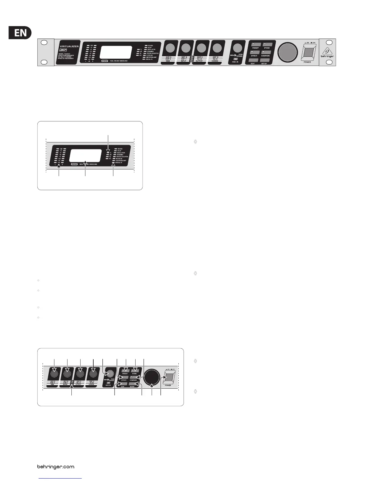
Fig. 1.1: VIRTUALIZER 3D front panel
The BEHRINGER VIRTUALIZER 3D’s front panel includes ve edit controls
(non-intermittent rotary controls), a jog wheel (big rotary control), six parameter
keys, an LED display and a mains switch. Each of the two fully independent
channels can be monitored with an 8-digit LED meter.
(1) (2)
(3)
(4)
Fig. 1.2: Display section of the VIRTUALIZER 3D
(1) Both the LED chains display the intensity of the input signal in dB in
relation to the nominal level, which is selected on the rear panel with the
OPERATINGLEVEL switch.
(2) After you switch on the VIRTUALIZER 3D, you can read the name of the last
used eect on the LED display. When editing, the LED display shows the
parameter’s name along with a 4-digit alpha-numeric display that shows the
absolute parameter’s value.
(3) To the right of the LED display are four STATUS LEDs which indicate the type
of value you are working with. You may do any of the following:
• set the absolute value of an eect parameter (“%”),
• increase or decrease the amplitude or determine the threshold point of the
compressor (“dB”),
• modify a frequency (“Hz”) or
• modify a time parameter (“sec”).
(4) The ALGORITHM GROUPS LED CHAIN indicates which category the
selected eect belongs to. Altogether the FX2000 oers eight dierent
algorithmgroups.
(5)
(13) (16) (18)(17)
(6) (7) (8) (9) (10) (11) (14)(12) (15)
Fig. 1.3: Function keys, controls and jog wheel
(5) Every preset in the FX2000 allows you to edit at least four eect parameters.
The EDIT-LED-CHAIN indicates which parameters are adjusted by the four
EDIT CONTROLs. If the top LED lights up, (6) controls the parameter EDIT A,
(7) controls EDIT B, (8) helps in changes of parameter EDIT C and with (9)
you change the setting of parameter EDIT D. If the middle LED of the EDIT-
LED-CHAIN lights up, the four EDIT CONTROLs modify the parameters that are
arranged to its left and right. The lower LED functions correspondingly.
◊ For the exact meaning of the individual effect parameters,
see chapter 7.1.
(6) With the 1st EDIT CONTROL (non-intermittent rotary control) you change
the values of the rst (EDIT A) and fth (EDIT E) eect parameters. You can
also select MIDI functions (MIDI) with the 1st EDIT CONTROL. Press the EDIT
key (13) to switch from EDIT A to EDIT E and vice versa. You reach the MIDI
function by pressing the SETUP key (16).
(7) The 2nd EDIT CONTROL allows you to modify the values of eect
parameters EDIT B and EDIT F. When you select the INPUT parameter with
the help of the SETUP key, you can specify whether the FX2000 functions
mono or stereo mode (see chapter 3.6.2 for more information).
(8) The 3rd EDIT CONTROL modies the values of eect parameters EDIT C,
EQLO, and the global OUTPUT parameter (see chapter 3.6.3). Here, as well,
you select among them using the EDIT and SETUP keys.
(9) With the 4th EDIT CONTROL, you modify the values of eect parameters
EDIT D, EQ HI, and the global parameter CONFIG (see chapter 3.6.4). Use the
EDIT and SETUP keys to choose between the parameters.
◊ During editing, you can rotate one of the four EDIT CONTROLs minimally
to display a brief description of the current parameter active. This can
help you know that, for example, EDIT A controls the pre delay for all
reverb effects of the VIRTUALIZER 3D. After approximately one second
the name is erased and the parameter’s current value is displayed.
This function can be used only by operating one of the controls that has
not yet been selected.
(10) By turning the MIX/BYPASS CONTROL the eect levels of most eect
algorithms are set in the range from 0 to 100%. If you select 0%, the signal
at the inputs of FX2000 is transferred directly to the outputs without adding
any eects (the signal is completely dry). If you select 100%, only the
eected signal is sent to the outputs (the signal is completely wet).
◊ If you use the FX2000 in the aux bus with your mixing console,
you should always set this value at 100%. if you’re using the FX2000
with a guitar amplifier (in a serial effects loop), we suggest settings
between 20 and 50% (depending on the amplifier type).
◊ Please note that, for the effects “parametric” and “graphic EQ”,
the MIX/BYPASS CONTROL allows a gain correction by rotation.
To bypass the FX2000’s eects, press the MIX/BYPASS CONTROL. Thisallows
you to compare between the original and the eected signals. Pressthe
MIX/BYPASS CONTROL again to deactivate the bypass and return to your
chosen eect. When the MIDI IN LED below the control ickers, itindicates
that MIDI data is arriving at the MIDI IN port.